Sanity Check on T6 Electrical System Design

Scottishstu

New Member
Hi everyone,


I’m in the middle of converting my 2018 VW T6 LWB and before I start ordering the remaining electrical components, I was hoping to get a sanity check from those with more experience.


The van currently has the factory leisure battery wiring under the passenger seat, so there’s an existing 10mm² feed from the engine bay. Rather than running a new cable, my plan is to use this and limit the Victron Orion XS to 30A.


Planned system


  • Fogstar Drift Gen2 230Ah underseat lithium battery (driver’s seat)
  • Victron Orion XS 12/12-50A DC-DC (limited to 30A)
  • Victron Blue Smart IP22 30A mains charger
  • Victron SmartShunt 500A
  • Eberspächer Zeliox ZCM6
  • 250A positive busbar
  • 250A negative busbar
  • 200A MEGA main fuse

12V Loads


The van will be running:


  • Dometic NRX50 compressor fridge
  • Autoterm diesel heater
  • 6 LED ceiling spotlights
  • 2 rear reading lights
  • LED ambient lighting
  • USB-A / USB-C charging sockets

I’m not fitting an inverter at this stage as I generally camp on hook-up or use portable power if needed, but I would like to leave provision for future solar.


ZCM6


Rather than using a traditional blade fuse board, I’m planning to use an Eberspächer Zeliox Control Module (ZCM6), which I was fortunate enough to be gifted.


From what I understand, it acts as a programmable 12V power distribution module with six individually protected outputs, replacing the need for a conventional fuse box. My plan is to use it to control and distribute power to the lights, USB sockets, fridge, water pump, etc.


If anyone has experience using a ZCM6 in a camper conversion, I’d be interested to hear your thoughts.


Proposed cable sizes


  • Battery → MEGA fuse → positive busbar: 35mm²
  • Battery negative → SmartShunt → negative busbar: 35mm²
  • Factory feed → Orion input: existing 10mm²
  • Orion output → positive busbar: 10mm²
  • Blue Smart → busbars: 10mm²
  • ZCM6 → busbars: 16mm²

Proposed fuses


  • Main battery: 200A MEGA
  • Orion input: 40A MIDI
  • Orion output: 40A MIDI
  • Blue Smart: 40A MIDI
  • ZCM6: 80A MIDI

230V System


The EHU inlet is mounted under the bonnet and feeds a consumer unit under the passenger seat. From there it supplies:


  • Victron Blue Smart charger
  • One 230V radial socket circuit

Questions


  1. Does the overall system architecture look sensible?
  2. Does the fuse strategy look sensible?
  3. Is 35mm² the right choice for the battery backbone?
  4. Are the 40A MIDI fuses appropriate for the Orion when limited to 30A?
  5. Would you use 10mm² or 16mm² from the Orion output to the busbar, considering it’s only around 0.5m?
  6. Is there anything obvious you’d do differently before I start ordering everything?

Thanks in advance. I’ve spent quite a bit of time researching this and want to make sure I’ve got the fundamentals right before I start buying everything. I’m happy to change the design if there’s a better or safer way of doing it.
 
A wiring diagram might help, but my initial questions would be:

1) Not seen a ZCM6 before but is it really designed to replace a fusebox? Fuses are very simple devices for a reason - there's not much to go wrong. If this is thing isn't giving you genuine functionality you actually need, I'd probably eBay it...

2) Not sure I understand how a positive busbar fits in? These aren't usually used because anywhere you would use one you would usually use a fusebox? The only scenario I can think of is where you're joining a bunch of wires of the same size/rating such that the incoming fuse protects all of them - this isn't very usual though, usually you're splitting off into smaller feeds, in which case you need protection (i.e. a fusebox) anyway?

3) I would probably cable/fuse the Orion up to its full rated output, feels a bit weird to rely on a software setting to prevent something blowing.
 
Oh, the other thing is that, technically speaking, a MEGA fuse may not be suitable for a large lithium battery because the potential short circuit current flow can be above the interrupt current of the device - an MRBF or class-T fuse is usually recommended for this reason.
 
  • Like
Reactions: EAN
Thanks both, I really appreciate you taking the time to reply. This is exactly the sort of feedback I was hoping for before I start ordering everything.


On the ZCM6, I probably didn’t explain it very well. It’s an Eberspächer Zeliox Control Module, which I was fortunate enough to be gifted. It’s essentially a solid-state power distribution module that replaces a traditional blade fuse box. It has six individually protected high-side outputs which can be configured and controlled (timers, dimming, voltage cut-off etc.), so my intention was to use it as the main 12V distribution for things like the fridge, lighting, USB sockets, and other house loads, rather than using a conventional spade fuse board. It’s then all run from an app with digital fusing setting etc.


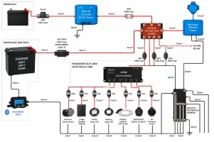
On the positive busbar, my thinking wasn’t to replace a fuse box with a busbar. The idea was simply to have a single distribution point after the main battery fuse, rather than stacking multiple large cables on the Fogstar battery terminal. Each outgoing circuit would still have its own fuse:


  • 40A MIDI → Orion XS
  • 40A MIDI → Blue Smart charger
  • 80A MIDI → ZCM6
  • Spare for future solar

So the busbar was really just there to keep the installation neat and make future expansion easier.


Regarding the Orion, the reason I was planning to limit it to 30A is because the van already has the factory leisure battery feed (10mm²) running from the engine bay to under the passenger seat. I was hoping to reuse that rather than pulling another cable through the van. I completely understand the point about not relying solely on software current limiting though, so I’m open to changing that if the better engineering solution is to cable and fuse it for the full 50A.


On the 35mm² cable, I’d be interested to hear your reasoning. The heavy cable runs between the battery, main fuse, shunt and busbars are all going to be very short (roughly 0.5–0.8m), and I initially chose 35mm² with the idea of future-proofing if I ever add an inverter but the chances of that are slim and will probably just use a powerbank. If you think 25mm² is a better choice for this setup, I’d genuinely like to understand why.


The comment about MEGA fuses vs MRBF/Class-T is also really interesting. I’d seen plenty of camper installations using MEGA fuses, but I wasn’t aware of the interrupt rating considerations with larger lithium batteries. If I was to downgrade to 105ah would that be a better suit to a MEGA fuss?
 
Thanks both, I really appreciate you taking the time to reply. This is exactly the sort of feedback I was hoping for before I start ordering everything.


On the ZCM6, I probably didn’t explain it very well. It’s an Eberspächer Zeliox Control Module, which I was fortunate enough to be gifted. It’s essentially a solid-state power distribution module that replaces a traditional blade fuse box. It has six individually protected high-side outputs which can be configured and controlled (timers, dimming, voltage cut-off etc.), so my intention was to use it as the main 12V distribution for things like the fridge, lighting, USB sockets, and other house loads, rather than using a conventional spade fuse board. It’s then all run from an app with digital fusing setting etc.


On the positive busbar, my thinking wasn’t to replace a fuse box with a busbar. The idea was simply to have a single distribution point after the main battery fuse, rather than stacking multiple large cables on the Fogstar battery terminal. Each outgoing circuit would still have its own fuse:


  • 40A MIDI → Orion XS
  • 40A MIDI → Blue Smart charger
  • 80A MIDI → ZCM6
  • Spare for future solar

So the busbar was really just there to keep the installation neat and make future expansion easier.


Regarding the Orion, the reason I was planning to limit it to 30A is because the van already has the factory leisure battery feed (10mm²) running from the engine bay to under the passenger seat. I was hoping to reuse that rather than pulling another cable through the van. I completely understand the point about not relying solely on software current limiting though, so I’m open to changing that if the better engineering solution is to cable and fuse it for the full 50A.


On the 35mm² cable, I’d be interested to hear your reasoning. The heavy cable runs between the battery, main fuse, shunt and busbars are all going to be very short (roughly 0.5–0.8m), and I initially chose 35mm² with the idea of future-proofing if I ever add an inverter but the chances of that are slim and will probably just use a powerbank. If you think 25mm² is a better choice for this setup, I’d genuinely like to understand why.


The comment about MEGA fuses vs MRBF/Class-T is also really interesting. I’d seen plenty of camper installations using MEGA fuses, but I wasn’t aware of the interrupt rating considerations with larger lithium batteries. If I was to downgrade to 105ah would that be a better suit to a MEGA fuss?

On the battery size - you'd have to look at the manufacturers specs and installation instructions. It's more to do with the short circuit current the battery will deliver in extremis than the size per se and lithium has extremely low internal resistance and so has the potential for very high short circuit currents. The battery itself may well have some built in protection though - best check with the manufacturer.

I still don't understand the positive busbar bit. If each circuit is individually fused (as it should be) then don't you just end up with a bunch of fuses hanging off a busbar - i.e. a kind of messy fusebox...?

On that 10mm2 cable, it would be convenient to use it - check the specs of that and the Victron, if it's 70A rated you might get away with it using a 60A fuse?
 
Nice diagram.

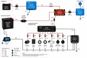
Given that does look like a bunch of fuses hanging off the positive busbar though, I still don’t understand why that’s not an actual fusebox to provided fused distribution?

It also seems to show a few fused positive feeds going straight to ground but I assume that’s just a an issue with the diagram rather than the actual plan!
 
Nice diagram.

Given that does look like a bunch of fuses hanging off the positive busbar though, I still don’t understand why that’s not an actual fusebox to provided fused distribution?

It also seems to show a few fused positive feeds going straight to ground but I assume that’s just a an issue with the diagram rather than the actual plan!
Wonders of using Ai for the diagram. I’m guessing more in line with this.

What would you use instead of the positive busbar? Do you have an example?

The positive busbar was to use instead of bolting all the positives to the positive peg of the battery.

Note that the fuses coming out of ZCM6 are programable internally so not actual external fuses as shown of the diagram.


8A04D5E2-FD3A-4AAD-9BA5-94B77905B997.webp
 
Last edited:
Wonders of using Ai for the diagram. I’m guessing more in line with this.

What would you use instead of the positive busbar? Do you have an example?

View attachment 331020

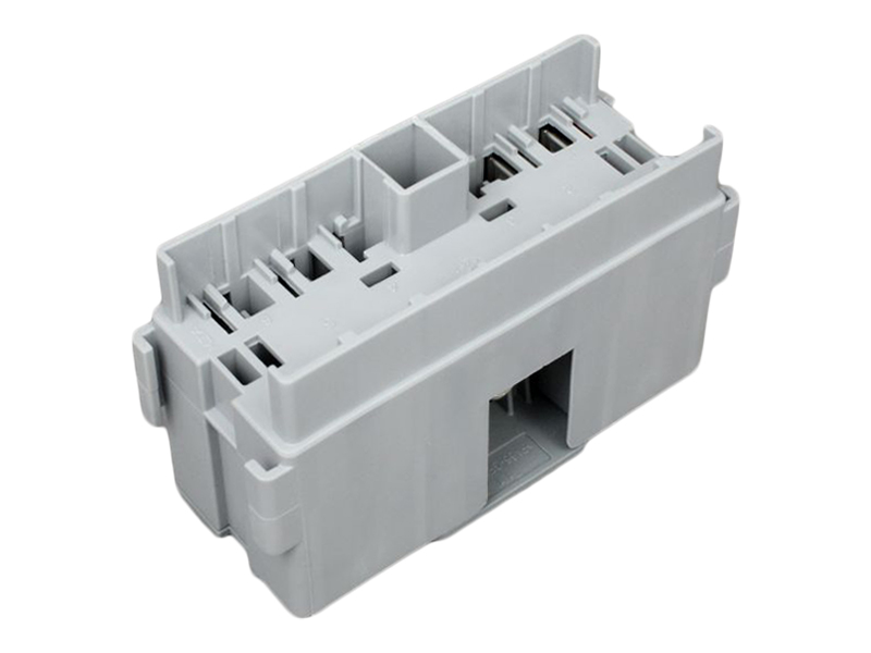
Any fusebox with a common in to multiple fused out will do, sometimes referred to as a distribution fusebox I think? Maybe you need midi fuses but you might also get away with maxi blades if they come big enough for what you need?
 
Any fusebox with a common in to multiple fused out will do, sometimes referred to as a distribution fusebox I think? Maybe you need midi fuses but you might also get away with maxi blades if they come big enough for what you need?

Something like this one maybe? You look like you only need three outputs so that would leave three spare. Check the max total rating though, given how chunky your main battery fuse is though (does it need to be that big?).

 
Back
Top