My wiring diagram - I would be very grateful for any feedback

sw25481

Member
VIP Member
Here is how I propose to wire my van. If anyone has a moment to take a look I would be very grateful if you spot I have made an error. Especially with cable sizes as there seems to be such variation in the advice.

I have sized assuming the only two long run are the connection from the alternator to the DC-DC converter and the wires from the roof solar however I have two captain seats so I may have to adjust when the batteries turn up if I can not fit everything.

I will add the 240v circuits and 12v loads in a later version but they are not expected to exceed 60 amps other than loads through the 2000w inverter which will include 1800w induction, 1500w kettle or similar obviously not at the same time.
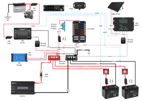
Van Electrics 27th Dec.png
 
Looks like you've put a lot of thought into this, good effort! I can see no errors.

My only thoughts (not criticisms) are;
  1. Assuming the 50a DC-DC is a DCC50S, why do you need a separate 20a MPPT charger? The DCC50S can do that for you.
  2. The cable from the alternator to the DC/DC doesn't need fusing at the DC/DC end as far as I'm aware.
  3. 16mm cable for the 30A EHU charger seems overkill, 6mm should be plenty.
  4. I used the chassis with it's multiple GND studs as my 'GND busbar', and that saves running large black cables around. The van body volt drop will be far less than any cable you can fit. Bad earth connections will cause terrible issues though, so you need to be make perfect connections.
  5. For my (fairly standard) layout, 2x 6 way fuse blocks put the fuses closer to the devices (fridge/heater/12v socket near the driver seat, lights/usb sockets/water pump near the rear).
 
Assuming the 50a DC-DC is a DCC50S, why do you need a separate 20a MPPT charger? The DCC50S can do that for you.

this is true for the DCC50s as it has a built in MPPT.

BUT,

as soon as you connect a panel to it, its splits into 25A (alternator) / 25A (solar) - even with 1w of solar

and with two 100ah Lithium's you would need that full 50A . . .

so it makes sense to run a separate 20A MPPT in this occasion, and keep the DC-DC for its full 50A


++++++++++++

on a smaller system you could use just a DCC50s with a switch in-line to disable any solar input as a boost switch to make the dc-dc go from 25A max to the 50A max.

++++++++++++
 
I’d fuse the 3 auxiliary (solar/dc-dc/mains) cables close to the +ve bus bar, potentially you could have the full fury of 2 Lithium batteries back feeding down those cables if any of them developed a fault.
 
I’d fuse the 3 auxiliary (solar/dc-dc/mains) cables close to the +ve bus bar, potentially you could have the full fury of 2 Lithium batteries back feeding down those cables if any of them developed a fault.

Understood. They should be all very close but if they are not I will pay attention to the location
 
this is true for the DCC50s as it has a built in MPPT.

BUT,

as soon as you connect a panel to it, its splits into 25A (alternator) / 25A (solar) - even with 1w of solar

and with two 100ah Lithium's you would need that full 50A . . .

so it makes sense to run a separate 20A MPPT in this occasion, and keep the DC-DC for its full 50A


++++++++++++

on a smaller system you could use just a DCC50s with a switch in-line to disable any solar input as a boost switch to make the dc-dc go from 25A max to the 50A max.

++++++++++++
Thank you Dellmassive, for this and the guides I based it on.
 
so it makes sense to run a separate 20A MPPT in this occasion, and keep the DC-DC for its full 50A
I had not thought of that. So with a 160W panel you could shove 50A+12A into the batteries, but.......

as soon as you connect a panel to it, its splits into 25A (alternator) / 25A (solar) - even with 1w of solar

and with two 100ah Lithium's you would need that full 50A . . .
I also got that information from Renogy, but it was a very unconvincing vague explaination they gave me. In the real world I'm almost sure that's its not true. My PV panel is always connected, and I've seen in excess of 40A going into the battery, but my solar never makes more than 10 or 11A even on the best days. Next time I'm driving in the sunshine, I'll get the numbers.

EDIT: I did get 29A total charge the other day while driving, the solar was giving less than 1A. This is the Renogy data, over modbus, not from a shunt, so it's not subject to any calibration errors. I'll try to repeat the test when the battery is at a lower SOC to get some bigger numbers.
 
Last edited:
That's a very similar set up to the one I've planned but I've a few questions.

1 - How do you stop the inverter draining the batteries too much? Is there a low voltage battery protect in the battery? If there is, why do you need a separate one on the 12v load?

2 - Are the cables to the inverter the right size? If so, wild camping at night you'll be using the battery only which is only 25mm cables. Should these be 35mm too?

3 - Where can you get a Renogy MPPT with a RC485 connection? I couldn't see it on their website.
1). Yes the Renogy 2000w inverter has a built in low voltage disconnect but so do the Renogy Smart batteries. I like having two so I added the Victron battery protect for the other loads.

2}. I have found sizing the cables to be difficult but here is what I have assumed. Will happily take advice, With a 2000w inverter you should size for 200 amps (Actual power draw would be 150 to 170 amps so there is some safety margin there). The cable runs from the battery to the inverter will be under 1m so I do not need to worry about voltage drop. 12voltplanet says 25mm is good for 170 amps but 35 is good for 240. The power will be drawn from both batteries and each battery only has the capability to provide 100 amps so I have gone for 25mm for the battery.

3). The one I bought was called the Rover Elite and it says it is no longer available. I must have got almost the last one. Their site is not working properly for me on my IPad at the moment but I will have a search again for you shortly.
 
I’d fuse the 3 auxiliary (solar/dc-dc/mains) cables close to the +ve bus bar, potentially you could have the full fury of 2 Lithium batteries back feeding down those cables if any of them developed a fault.
sorry to raise this back from the dead but as im following the same guide for my van, can you explain to a simpleton like me what you mean by this? cheers pal
 
If you look at the alternator there are 2 70A fuses at each end on the wire. The same could apply to the 3 wires going into the busbar. The diagram above shows fuses near the leisure batterys and inverter but to be ultra safe you could also add the same rated fuses at the busbar end of these connections.
 
sorry to raise this back from the dead but as im following the same guide for my van, can you explain to a simpleton like me what you mean by this? cheers pal
If you look at the drawing, the 3 aforementioned cables have protection (breakers/fuses) but the protective devices are at the end away from the bus bar. If any of those cables developed a fault between the +ve bus bar & the protective device, the only things protecting those cables are the 2 X 125A fuses at the batteries. You could potentially have 250A fault current flowing down a 6mm (solar charge cable) before anything blew. 250A down a 6mm cable = fire. Those cables need fusing as close to the bus bar as possible. Ideally a fused bus bar should be used.
 
If you look at the alternator there are 2 70A fuses at each end on the wire. The same could apply to the 3 wires going into the busbar. The diagram above shows fuses near the leisure batterys and inverter but to be ultra safe you could also add the same rated fuses at the busbar end of these connections.
thank you, i understand now. so ill make sure i get my fuses to the busbar end. how much distance should i have between the negative and positive busbars?
 
If you look at the drawing, the 3 aforementioned cables have protection (breakers/fuses) but the protective devices are at the end away from the bus bar. If any of those cables developed a fault between the +ve bus bar & the protective device, the only things protecting those cables are the 2 X 125A fuses at the batteries. You could potentially have 250A fault current flowing down a 6mm (solar charge cable) before anything blew. 250A down a 6mm cable = fire. Those cables need fusing as close to the bus bar as possible. Ideally a fused bus bar should be used.
thanks pal. very helpful. do you happen to know how i find a earth stud or point near the rear wheel arch behind driver?
 
thank you, i understand now. so ill make sure i get my fuses to the busbar end. how much distance should i have between the negative and positive busbars?
Just to be clear, to be ultra safe, there should be fuses at the 2 battery sides AND fuses near the 2 busbar sides. So 2 fuses at each end of the battery wires, just like the alternator wire is. 2 fuses on the inverter too, but this isn't as crictical as the battery wires but better safe than sorry. If you do only use one fuse on the inverter I'd recommend moving it closer to the busbar rather than close to the inverter. As for busbar distance, you want to avoid arcing, so I'd say 2 inches AND/OR insulate/cover the posi busbar.
 
Back
Top