Led Light Glow Courtesy Setting.

Buzznitro

Member
T6 Pro
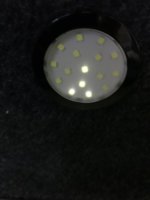
Morning All, went camping at the weekend and I found an issue With my interior lights, I have my lights switch through my courtesy wiring, and have linked a direct feed from my leisure batteries for permanent live but when my courtesy lights are in the on position and when the timed goes out I still see some of the LED lit up, they only go off completely when turned off, can anyone help please.
Thanks in advanced

5611371F-681C-47F3-9CC7-E8204FB31487.jpeg

3998DBA4-94D8-4DE1-83F7-FB6A37BC513B.jpeg
 
thats a common problem with a lot of LEDs, (normally the cheaper ones) as @Ads_Essex mentioned.

its not enough to flatten your battery, just very annoying in my case.

i ended up swapping the lights out for a different brand to solve my issue, but there may be other ways of stopping it,

i think one was might be to fit a 12v-12v / dc-dc regulator circuit PCB to the LED feed lines,

that way the LEDs will only power up when the DC/DC Regulator gets enough power to switch on. and stop the power bleed via the BCM,

of fit a second inline on/off switch - buts that prob just as annoying.
 
Thanks everyone I have a regulator from Travelvolts I’ll put it inline from my leisure battery feed see if this works.
 
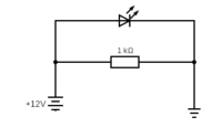
It's down to the circuitry in the BCM and the way it dims the lights down. Fit a 1k resistor between the positive/negative on the light circuit and this will stop the led's glowing
 
It's down to the circuitry in the BCM and the way it dims the lights down. Fit a 1k resistor between the positive/negative on the light circuit and this will stop the led's glowing
That's interesting..... I'll have to try that.
 
Forum shop one dont do it....

But next time I see someone with the issue.... I'll try a resistor idea.....
 
Ok. Was going to get forum shop ones, as I’m sure I read in a previous post that these worked for you but really wanted warm white.
 
Hi Deaky, could you draw me a sketch I think I know what you mean but I’m a picture man words don’t always work in my head
 
Hi Deaky, could you draw me a sketch I think I know what you mean but I’m a picture man words don’t always work in my head

circuit.png

If your connected to the courtesy circuit then +12v will be the red/black wire and -ve will be brown/red wire
 
i assum the resisitor is to load the circuit just enough to get the bcm to switch them off
 
So I assume the resistor can be placed as close as possible to the LED light connectors?

Trying to remember my electrical engineering course - far too long ago!!! What power will that resistor pull from the Leisure battery as a parasitic load when everything is off?


Is it as simple as this - so negligible?

W = V2 / R (Ohms)

0.144 W = 12*12 / 1000
 
Tried to edit message above but wouldn't let me ...

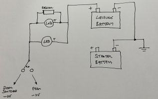
I encountered the same issue, initially I tried to be clever thinking about a relay to isolate circuits but conversion shop said if I combine earths on Leisure and Starter Battery then having three way operation of the light while powered by Leisure battery was relatively simple. They set it up and all looked good until I saw the feint glow at night when doors locked. I assume they wired as below.

So to stop the glow, I assume the resistor can be placed as close as possible to the LED light connectors?

OR Wait .... is it more complicated than that when using +ve from Leisure Battery and 3 way switch (Door Operated, Always on, Always off) - Does following proposed diagram look right for resistor position? @Deaky @Dellmassive
IMG_3034.jpeg


Trying to remember my electrical engineering course - far too long ago!!! What power will that resistor pull from the Leisure battery as a parasitic load when everything is off but small current leak through BCM Door Switched -ve?

Is it as simple as this - so negligible?
W = V2 / R (Ohms)
0.144 W = 12*12 / 1000


Or is it even less than that, because the VAN BCM Door Switched -ve restricts it further?

 
You could fit the resistor just to + and door switched -ve you don’t need a resistor for the perm -ve as it’s physically open circuit when not in use so no leakage j how you’ve drawn it above is still ok though.

Power drawn will be much lower I think you want to base it on p= I x V where I is going to be the tiny parasitic current draw through the BCM
 
Back
Top