inverter not registering draw on shunt

Epic-Rob

Kiwi member
VIP Member
T6 Guru
ok so my Voltronic shunt is registering draw from lights and deisel heater etc, and also showing charge from solar and DCDC
but when i switch the 1200w victron inverter on with the induction hob (or any load) no draw showing.
what it will do is briefly flick to showing a charge of something like 10a then just revert back to what it was before.
the voltronic shunt is 200a so wont be overloaded by the draw from induction hob.

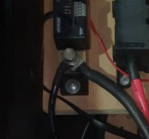
looking at the pic bellow
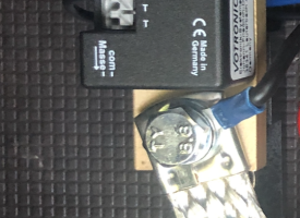
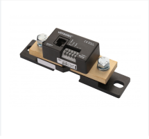
the 2 black cables on same term, one of those is coming from the DCDC charger, the other is going to the shunt.
i have the neg cable from the inverter conected directly onto the battery side of the shunt, i have switched it onto the BMS but it didn't make any diff. earth side of shunt is directly to a seat bolt on floor.

poss for inverter is going directly to pos on battery through a mega fuse.

I am sure it will be something simple.......
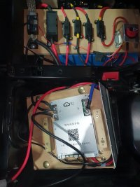
20230626_134609.jpg
 
Hi,


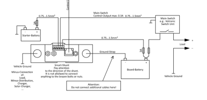
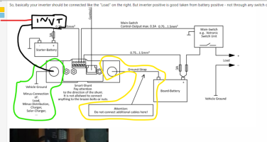
You have two black wires on shunt battery side. There should be only one and that should go to the leisure battery negative. Note how even Votronic manual notes that there should not be additional wires connected to the battery negative or shunt battery side.

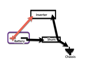
So, basically your inverter should be connected like the "Load" on the right. But inverter positive is good taken from battery positive - not through any switch due to the large load.
1687756128202.png
1687756682159.png
 
The inverter NEG need to be the other side of the shunt. (Shunts work by metering the power through the neg side of the circuit)

Either chassis, or shunt load side, or neg busbar.

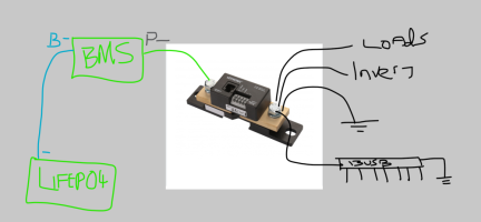
As above, the only thing connected to the battery NEG post (effective your BMS NEG OUT as your BMS is external) should be the battery.

So it's.

Cells neg -> BMS cell neg -> BMS NEG out -> shunt neg for battery -> shunt neg to chassis and everything else.

.
 
Fyi

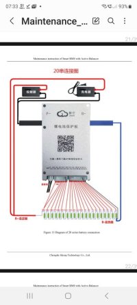
B- is battery neg so goes to your cells NEG.

P- is power NEG so goes to your shunt..... Then on to all your system negs.


.

Screenshot_20230626_073316_Samsung Notes.jpg

.
 
Hi,


You have two black wires on shunt battery side. There should be only one and that should go to the leisure battery negative. Note how even Votronic manual notes that there should not be additional wires connected to the battery negative or shunt battery side.

So, basically your inverter should be connected like the "Load" on the right. But inverter positive is good taken from battery positive - not through any switch due to the large load.
View attachment 203527
View attachment 203530
I did take the inverter wire off here and connected it to the P- it made no diff
Hi,


You have two black wires on shunt battery side. There should be only one and that should go to the leisure battery negative. Note how even Votronic manual notes that there should not be additional wires connected to the battery negative or shunt battery side.

So, basically your inverter should be connected like the "Load" on the right. But inverter positive is good taken from battery positive - not through any switch due to the large load.
View attachment 203527
View attachment 203530
 
The inverter NEG need to be the other side of the shunt. (Shunts work by metering the power through the neg side of the circuit)

Either chassis, or shunt load side, or neg busbar.

As above, the only thing connected to the battery NEG post (effective your BMS NEG OUT as your BMS is external) should be the battery.

So it's.

Cells neg -> BMS cell neg -> BMS NEG out -> shunt neg for battery -> shunt neg to chassis and everything else.

.
Sorry not quite following you on that. as it is in pic the battery side of shunt has the earth from P- and the earth from the Inverter. there is only the earth strap on the earth side of the shunt.
Are you saying i should have the inverter connected to the other side of the BMS, B- ?
 
Only the shunt should be connected to the battery negative.
All other negatives should be on the other side of the shunt.
 
Only the shunt should be connected to the battery negative.
All other negatives should be on the other side of the shunt.
you mean on the earth strap side of shunt? but wouldn't that then be bypassing the shunt?
 
You need to think of the (battery + shunt) as one entity - The positive terminal is the Battery + The negative terminal is the shunt com-
 
Sorted.
110Ah draw on my 1200w induction hob but i have a 230Ah battery so that will be fine
inverter draws 2.4Ah in standby.
Thanks all

Is an interesting one though because in my other van all loads inc inverter are connected to battery side of shunt and not earth side and it registers fine on the shunt display.
 
Back
Top