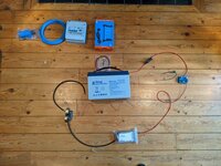
Electric layout

Graeme_B

Senior Member
VIP Member
T6 Guru
PXL_20210122_134209604.jpg
Just laying things out (I know its not a clear diagram but it helps me) to make sure i have everything in order before starting installing.

Am i missing anything?

I've also got the ablemail ams to connect in too (waiting of wiring kit), the loads from the Fuse box and sockets from consumer unit but that can wait another day.

Was thinking CU, battery charger and Ablemail under passenget seat with battery, battery protector, fuse box and smart shunt under drivers seat.

Any thoughts?
 
I was considering CU and fuse box under driver with battery, smart protector, dc to dc, mains charger and shunt under passenger but don't think it fits easily so switching. PXL_20210123_135135732.jpg
 
Is there any reason not to put chargers on their sides?

I've got Ablemail AMS 12 12 30 and victron 12 30 chargers. I've fiddled about enough and come to the solution for underseat electrics all under driver seat leaving consumer unit under passenger.

my initial idea was the reverse but already quite a bit wiring in passenger but this seems to work.
PXL_20210123_154946161.jpg
 
Sorry should of probably added this to my other post re electric layout. If a mod sees please feel free to merge them thanks
 
No problem at all with doing this. With components that tightly packed, make sure you are maximising the possible airflow around them by leaving the biggest gaps you can.

Pete
 
@Pete C cheers. I'm planning on a some kind of ply framework to fix them in and max space between them. There was a mounting bracket in under the seat i was thinking of repurposing but it just doesn't fit.
 
That’s a lead acid battery. It shouldn’t be on its side.
 
@Deaky just looking at the user manual for battery and only mentions not to put it upside down. Also, checking travelvolts site and seems to show other lead AGM batteries on side.

I'm not well versed in this kind of thing and with help of forum am learning all the time - is it strictly all lead batteries that should be upright or could some be suitable?
 
Just taken from manufacturer:

Absorbed Glass Mat (AGM) batteries are dry-cell, with the battery acid being encapsulated in fibreglass sheets. In comparison to flooded batteries, AGMs offer increased levels of reliability and versatility – with no free acid, they can be mounted in any orientation and are better able to handle vibration.

To be fair from simply looking at battery it doesn't say it is AGM so thanks for looking out for me.

This is a learning curve for me, i really appreciate all the tips and advice from the forum and I know I'll never mount a wet lead battery any way than upright!
 
I am coming round to conclusion of putying 12v distribution further back in the van as will save ventilation space and mean running +ve and -ve 6mm cables from under the seat and up the b pillar.

@Pete C noticed reading a past post this is similar to your setup. Do you use a smart shunt? Just trying to figure out what additional connectors I'd need.
 
Yes, 12v fuse box is further back in the van as that is where most of the 12v items are.
I don’t have a smart shunt - I would like to fit one, but not critical at this stage, and saving money for the next VW project.

Pete
 
Also, to add, I have never understood why people put fuse boxes under the seat. If you blow a fuse, then you might end up having to remove the seat to replace it.

Pete
 
Also, to add, I have never understood why people put fuse boxes under the seat. If you blow a fuse, then you might end up having to remove the seat to replace it.

Pete
Ha, once they go back on i don't fancy takimg them back off either!
 
The trick is to position the fuse box where you can easily see and reach it through the front or via the rear clip on cover in the seat box.
 
No need to run -ve cables to the rear, just use the earth studs in the van
I'm running a smart shunt - think ot would require all -ve to flow through this to battery -ve. I'm not 100% on this at the moment.
 
I'm running a smart shunt - think ot would require all -ve to flow through this to battery -ve. I'm not 100% on this at the moment.
So connect the battery neg ONLY to the shunt, and the other end of the shunt to bodywork. Then all devices use vehicle body as their negative connection. That way all battery current passes through the shunt.

I would think this is the standard way to do it, and it works for me.

PROS of using vehicle body for return path;
save money on cable
save space on cable runs
less volt drop, if done properly

CONS of using vehicle body for return path;
?
 
Back
Top