You are using an out of date browser. It may not display this or other websites correctly.
You should upgrade or use an alternative browser.
You should upgrade or use an alternative browser.
Dodgy Demister
- Thread starter andys
- Start date
-
- Tags
- heated rear window
that looks familiar to what i was looking at today,
but i didnt notice anything obvious that might be related.
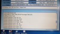
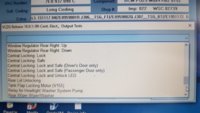
Done these output tests now, just the same.im thinking:
try adding bit-5 and restest the output tests,
then
try removing bit-2 and restest the output tests,
(i dont see what the CAN has to to do with HRS as the switch and element are both connected to the BCM, unless its looking for other inputs or data from the CAN Bus....... but saying that mine shows the VIA CAN enabled also)
i had a similar issue when i added HID lights with auto leveling on a T5.1 - i messed up the coding, its was via the LIN Bus not via CAN. seperate issue but demonstrated how flipping just ONE BIT can mess up the settings.
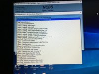
I did look through the adaptation channels yesterday but couldn't see anything. I've never altered anything in the adaptation channels.
Some fairly damning evidence that it's not coding though, I found the coding for the BCM from the first autoscan I took when I got VCDS in 2017 before I changed anything at all, and the value in Byte 15 was 0xD4, exactly the same as now, and the rear screen workd fine then.
I then put this exact coding for the whole BCM into VCDS, i.e. restored it to factory setting and it still didn't work...
My previous MY16 van (with HRS) had earlier revision of BCM - no suffix at allanother difference i noticed was mine have C and yours had B (7E0 937 090 B/C)
Part No SW: 7E0 937 090 HW: 7E0 937 090
Component: BCM PQ25 Max4 H80 0736
The current van (with HRS) has the same BCM as @Dellmassive
Part No SW: 7E0 937 090 C HW: 7E0 937 090 C
Component: BCM PQ25 Max4 H82 0752
So @andys BCM falls just in between - even the software revision H81 0744
any one got the full BCM J519 pinout list?
im sure i had one but cant find it.
im sure i had one but cant find it.
Thanks, I'll go through those tomorrow nightBrain-fried-.com
i think its time to go back and double check all our powers and grounds for the BCM (which seems to be supplying the source power for the Z1 HRS via one of its many input fuses).
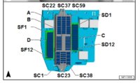
time to test ALL the fuses, and especially these ones that list the J519.
View attachment 38418 View attachment 38419 View attachment 38420 View attachment 38421 View attachment 38422 View attachment 38423
Do your Testing with the ignition on and the van running.
Do not pull out the fuses.
Use a test light or multimeter to touch the exposed metal spots an the top of the fuse in situ. Testing both sides of each fuse.
You should read battery voltage at both spots.
Some fuses might not give you a reading untill the circuit is turned on. So switch on stuff untill you get a reading.
Draw out a list on paper and record your readings across all the fuses on the under dash Fuse box.
Do You have fuses under the seats to?
Wiggle each fuse in turn and keep testing the HRS button to see if it fires up.
The next step will be testing at the BCM but we need the pinout it list first.
.
Last edited:
Like this -->
Love this guy.
.
Love this guy.
.
And here..
.
.
Well I've done the fuse check. I find it really difficult and painful to squeeze into a lying down position betweeen the seats so that I can see the fuses in the centre console due to previous back and arm injuries. Even harder to then get my fingers in and keep a light on what I'm doing. But it's done so here goes, from my notes
1) I was unable to check SC 2,3 and 4 (SC1 aux coolant not present on my van) as they don't have exterior test points and I couldn't get my fingers in to remove them. However, using the labelled Fuse Card photo that @Loz uploaded I was able to identify that the functions they supply are working fine so I can deduce that they're fine. Same with SC 38, 39 and 41 which handle ignition and lights which are fine.
2) All other SC fuses tested fine, showing voltage at either side, with the exception of the 5A in SC57. I swapped this with another fuse and it still didn't have power to either side. Closer examination showed that there were no actual metal contacts behind and the fuse had just been wedged into the plastic! Again referring to the fuse card, this turns out to be for rear aircon which I don't have.
3) Unlike the fuse card photo, SD 6, 7 , 9, 10, 11 and 12 are populated on mine and all have metal contacts behind, however the only one that was receiving power was the 25A in SD9 which was live on both sides. With ignition off the others tested fine for continuity, but had no voltage to either side regardless of ignition status.
4) Another difficult task was wiggling the fuses while pushing the HRS button as I kept having to unfold myself out to be able to see where I was pressing, but I managed it in the end with no response.
So it doesn't look like this has revealed anything
@mmi Confusing part is the mysterious, steady 5.7 Volts.
that voltage was with the HRS - DISCONNECTED - so no current flow/voltdrop,
its the 5v reference voltage that the BCM is putting out on the output wire to check for short to ground or short to power etc (using the internal pull up resistor inside the BCM)
Spent a sleepless night...Yes, when the heater element is disconnected - there is a kind of 5.7 V on the left connector. Actually it seems to be a pulsed signal at 200 Hz - need to have closer look into using a scope. Anyway, the important part is that a regular multimeter shows 5.7 V. I think this suggests that the +feed wiring is connected all the way up to the BCM.
Open circuit 5.7 Volts actually looks like this - peaking at 11 Volts, the pattern repeating at 10 ms intervals. Now regular multimeter readings have a decent explanation - a regular multimeter "averages" to 5.7V, and looks like it catches a spike to make it look like 200 Hz.
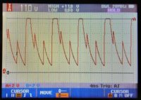

Anyways, does the above make any sense - not really I would say - just an open end of a circuit "vibrating"... But definitely looks like this high voltage is an indication of open circuit.
----
So loaded the HRS circuit with a 1000 ohm resistor to see what the BCM is trying to do. Apologies that time scale is different below (2 ms/div instead of 4 ms/div above).


So what we have now when the HRS circuit is loaded with 1000 ohm resistor (instead of heating element of about 0.5 ohms drawing about 22 Amps).
Now the voltage is peaking up to (only) 1.05 V thus a huge drop in voltage compared with just open circuit. Obviously can be used to detect open circuits.
If the same scheme is used on all circuits this would explain my glowing license plate LED lights - till shutdown of the BCM. Which actually happens already about 45 seconds after locking the van. I have to admit that I was not expecting this to be active without ignition being on - these were measured ignition OFF.
And lastly, the open circuit fault did not clear by reconnecting connectors or or even starting the engine and driving around. However, I would expect it to clear itself eventually.
Sorry that this either really doesn't help resolving the problem.
Great scope work, the circuit test almost looks like a PWM signal when you loaded it...
I doubt the HRS is PWM driven, I would assume it was just hard ON....?
Anyone got a T6 BCM/J519 pinout It list?
Still realy strange, looks.like his HRS is connected correctly and is detected when unplugged?
I was hoping he would fine a BCM fuse/supply issue.
So it's direct to the BCM next.
Best do some Yoga @andys ..... your gona be bent double. =]
Last edited:
The last time I did any work with the BCM I got stuck upside down in the footwell and couldn't straighten up for the rest of the dayGreat scope work, the circuit test almost looks like a PWM signal when you loaded it...
I doubt the HRS is PWM driven, I would assume it was just hard ON....?
Anyone got a T6 BCM/J519 pump It list?
Still realy strange, looks.like his HRS is connected correctly and is detected when unplugged?
I was hoping he would fine a BCM fuse/supply issue.
So it's direct to the BCM next.
Best do some Yoga @andys ..... your gona be bent double. =]
Calling All T6F crew,
Let's try and help out @andys
We need a T6 BCM (J519) pin-out diagram/list.
Or ask your local tech or dealer . . . .
Why his heated rear screen isn't working. (The HRS button light just flashes up for a second then goes out. All fuses ok. And HRS supposed ok)
Let's see if we can club together and get it fixed. =)
Has the switch been replaced yet? Maybe it just isn't latching on and/or not sending a long enough signal. ( Starting with the simplest item first - I haven't a clue as to what signal is sent by the switch or looked for by the BCM. Heaters I can cope with but all this BCM wizardry is alien to me  )
)
Hmm that’s a possibility. I wonder if the AC or recirc switches have the same contacts on the back so I could pop them out and try one of those and see what happens?Has the switch been replaced yet? Maybe it just isn't latching on and/or not sending a long enough signal. ( Starting with the simplest item first - I haven't a clue as to what signal is sent by the switch or looked for by the BCM. Heaters I can cope with but all this BCM wizardry is alien to me)
Similar threads
- Replies
- 6
- Views
- 1K
- Replies
- 0
- Views
- 189
- Replies
- 10
- Views
- 460
- Replies
- 30
- Views
- 4K


