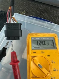
The easiest way to test the CAN bus without an oscilloscope is to check the termination resistance. Disconnect your battery, unplug the radar, and use a basic multimeter to measure the resistance between CAN-H and CAN-L. You should see a reading of 60 ohms.
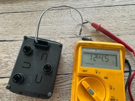
Getting 120 ohms on the harness means the other termination resistor isn't on that part of the CAN-BUS. The radar unit itself might act as the terminating node. Can you take your multimeter and measure the resistance across the CAN-H and CAN-L pins directly on the unplugged radar?
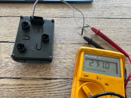
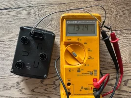
After leaving it and testing again (5 mins later) it seems to have settled at 131.4 ohms, if I leave the multimeter connected, now it is slowly increasing as I watch it (currently up to 136.3 ohms)
Found this online - might explain the value climbing :
Resistance increasing while you are taking a measurement often indicates that you are measuring a capacitor or a circuit containing one. This is usually a normal function of the component, not a sign of failure.
Why Resistance "Climbs"
When you use a multimeter to measure resistance, it sends a small amount of current through the component.
Capacitor Charging: A capacitor stores electrical energy. As the multimeter’s current flows into it, the capacitor charges up.
If you plug your radar back in place and then gently pierce the insulation of your CAN-BUS wiring and measure the resistance I expect you to see resistance reading close to 60ohm.
But anyway so far you have verified power supply and CAN-BUS wiring integrity.
Next step would be checking network wiring and the communication. This is going to be very tricky without specific equipment.
Thanks @Robert - agreed, testing the Ethernet side will be tricky. Since reading quite a few VW forums (with similar issues) I think you might be correct, the radar is kaput..
I am booked in with VW for diagnosis in 3 weeks. I have heard they can suggest a faulty radar is a ‘wear & tear’ item and therefore not covered under warranty..
Very happy to report back that this fault was successfully repaired by the amazing team at VW Liverpool. It was a faulty radar (J428 module) sensor. VW Liverpool used to look after our Transporter and were always fantastic, we received the same top level service from them with our Buzz too!
This site uses cookies to help personalise content, tailor your experience and to keep you logged in if you register.
By continuing to use this site, you are consenting to our use of cookies.