Halo + LED interior lights

BrenR

Member
VIP Member
T6 Pro
Hi, I am fitting a halo roof in the rear and looking to wire the LED lights on a 3 way switch - to come on when doors are open, off and on. I don't currently have a leisure battery fitted, but would like to add a switch to have on / off for the leisure battery.

I would also like to wire the halo led strip light now. Can I 't' off the on from the main battery live for the LED lights, but wire into a three way switch so that I can add the leisure battery later (next month?

TIA.
 
All the switching is done in the -ve side. Connect it to your courtesy circuit like the OEM lights are connected at the moment. When you fit your leisure battery, remove the halo +ve from the OEM wiring and connect it to the leisure battery
 
Sub, depends on wattage and Amp draw.

As a guide its 10A per 100w power.

Its always best to take the main feed directly from the starter or Aux battery via a fused appropriately gauged cable. (Then chassis groumd)

Sub and heater depends on physical size.... you might have trouble fitting both in the same location...
 
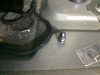
Yes, you may need to rub off any paint.

Make sure you have a good clean metal to metal connection.. maybe fit a couple of washers.?
 
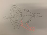
Is it as simple as this? (original copied from the three in top link).

Many thanks for the replies and appreciate the advice.

View attachment 93004
That won't work, It will switch all the lights on. You will need to isolate those two lights from the others with a couple of diodes
 
yes/no.

the simple switch yes, but as @Deaky said if you plan on "REUSING" the same LED lights that are also controlled via the same other rocker switch . . . then either blocking diodes or a relay will be needed to isolate the back feed from the second switch.

but . . .

if you plan to use "DIFFERENT" additional LED lights for your reading lights (thats what i assumed at first) . . . then just the switch will work.

whats you plan? same as the diagram above . . . . to have a duel use for a couple of the lights?

The plan was dual use, my initial thoughts were using single reading light in the middle on a separate switch, but now wondering if it will look too busy and an after thought.
 
gotcha . .

maybe look at something like this. (not tried it myself, but i think it will work)

break off the -0ve/negs for the two lights you want to "duel-use" . . . . . and run them through a relay.

the relay will have

COM-(comon)
NO-(normaly open)
NC-(normaly closed)

then the coil contacts +ve & - ve

**

run the light negs via the relay to switch between the common grouns with the other 4x lights and a new 0ve chassis ground.

you will need a second switch, use this to power the relay 12v on/off.

Note: if you use the same +12v that feeds the lights for the relay its timed!! so will switch off after the timer.

take if from a 24/7 +12v supply or even better a leisure battery . . .


***************************************************************************************
Factory Non-LED 3 wire setup:

(brown) - earth point left a-pilar
(brown/red) - connection 1 main harness (BCM switched neg 0v)
(red/black) - positive connection 1 main harness (BCM timed +12v) ( 7.5A fuse 24 holder C)
****************************************************************************************
Factory LED 2 wire setup:

(brown/red) - connection 1 main harness (BCM switched neg)
(red/black) - positive connection 1 main harness (BCM timed +12v)( 7.5A fuse 19 holder C)

****************************************************************************************


1606329159812.png


...


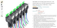
have a look at these relay options . . .


1606329641959.png


.


1606329677053.png


..


1606329726535.png


.


1606329772494.png

.


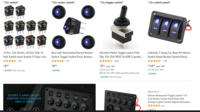
and a 12v switch like any of these . .


1606329841983.png


...
 
on the same subject;

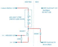
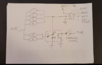
I'd like to make a similar mod on my T6.1 (without relays/switches) and I think I understand how to do it, here's my plan;

1606497284058.png

I had 2 black connectors which used to feed the load area lights, I re-fitted one of the lights near the tailgate.
The 0V from the spare plug, I will use to turn on the new slide door light, to prevent my MOSFET from turning on my tailgate light.
The 12V from the spare plug, I will leave unused.
This will mean the LED strip light/courtesy light will always get power from the leisure battery, and never time out (like the BCM 12V does?)

Does this seem alright? Or is there a better way? Will the BCM handle one (of two) original lights, plus the new 300mA led light strip?
 
Last edited:
I can't comment on the current rating of the BCM other thanto say that it's rated for incandescent festoon bulbs, so if you've replaced those with LED bulbs then you shouldn't be exceeding the BCM current rating. If you wanted to be on the safe side you could replace the diode with another MOSFET switch module which would run in parallel with your MOSFET circuit. See attached diagram. That way there will be no appreciable load on the BCM
 

Attachments

  • Simple Courtesy Light Switching.pdf
    102.9 KB · Views: 20
The interior light circuit is fused at 7.5A, so thats the MAX you can switch through the BCM.

You can use the "+12v timed BCM supply" or a AUX leisure battery supply (must all have common chassis grounds)


***************************************************************************************
Factory Non-LED 3 wire setup:

(brown) - earth point left a-pilar
(brown/red) - connection 1 main harness (BCM switched neg 0v)
(red/black) - positive connection 1 main harness (BCM timed +12v) ( 7.5A fuse 24 holder C)
****************************************************************************************

Factory LED 2 wire setup:

(brown/red) - connection 1 main harness (BCM switched neg)
(red/black) - positive connection 1 main harness (BCM timed +12v)( 7.5A fuse 19 holder C)

****************************************************************************************


you can use the Relay method or Mosfet method as @Mccoatup has shown above.


as for your idea . . . . what are you going to run on the Arduino?

how will you switch the light on/off?

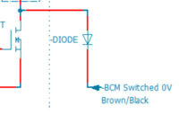
what is the purpose of this Diode?


1606499309932.png


.


FWIW I've just grabbed some of these Mosfet driver boards to start testing.

they are rated 4-27V @ 10A so look good. . . . but id like to see how hot they get when drawing 3A - 7A of expected LED load. (ill post test results)


Application: output port can control high power devices, such as motors, lamps, LED lamp strings, DC motors, micro water pumps, electromagnet valves; it can input PWM to control motor rotate speed and the brightness of lamp

Interface:
1. DC+: device DC power positive
2. DC-: device DC power negative
3. PWM: signal input port (connects MCU IO ports, PLC interface, DC power)
4. GND: signal negative port
5. OUT+: output port positive (connects device positive)
6. OUT-: output port negative (connects device negative)

Specifications:
Model: YYNMOS-1 (input and output are completely isolated)
Input Signal: 3-20V PWM signal
Output Capacity: DC 3.7-27V, and the current is within 10A
PWM Frequency: 0-20KHz
Size: 3.7x2.3cm/1.46x0.91"
Quantity: 1 Pc

Note:
Please allow 0-3mm error due to manual measurement. pls make sure you do not mind before you bid
Due to the difference between different monitors, the picture may not reflect the actual color of the item. Thank you!

No Retail Package
Package Includes:
1 x Driver Board


.
 
Back
Top