Hi I’ve invested in a victron pure sine wave inverter for charging my lap top and charging an ( battery powered ) acoustic guitar amp .. I’m not looking to run battersea power station or cook with my set up . I just want a very clean 240v supply for some occasional high tech gear that I use .
Basically I’ve done a lot of my wiring myself but I’ve got to the point where I have to admit I’ve still a lot to learn about dc wiring in vehicles .
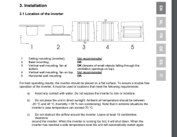
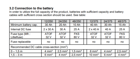
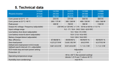
I have my 240 hook up sorted ( fitted for me ) that’s all sorted . I've then installed a solar set up .. a fridge (dc) and now i need to wire in my inverter . Hopefully these pics will be self explanatory. I’m just looking for advice on wire Guage ( I’m thinking 6 mm 10awg ) position and mounting of inverter . Should I add a little additional dc consumer unit etc etc. I’m going to incorporate existing sockets but have the inverter separate ( floating ) from my standard 240v hook up .
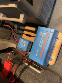
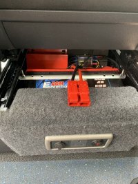
Here’s the pics first pic is my basic under drivers seat set up with an Anderson connector that then leads to the rest of my less well organised gubbins .
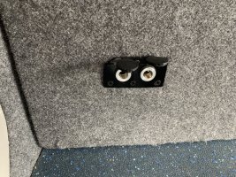
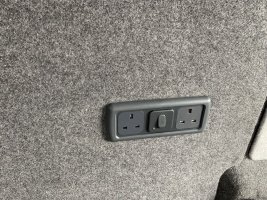
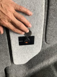
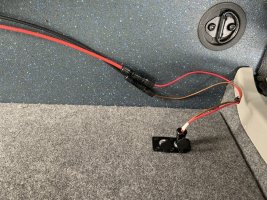
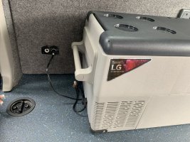
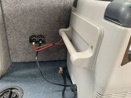
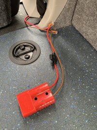
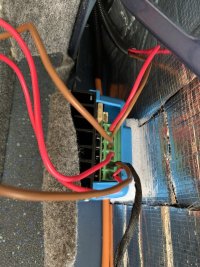
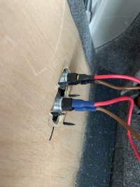
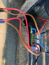
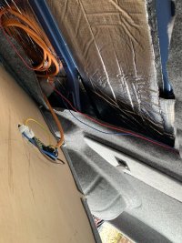
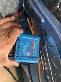
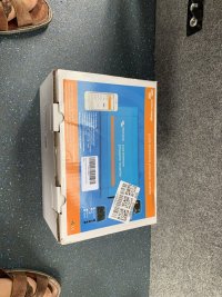
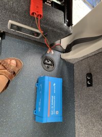
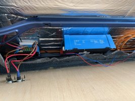
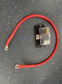
I’ve got to the point where I’m thinking hmm .. this Halfords 27 amp cable is probably not the best stuff to use . I’m good to the Anderson connector it’s from here on that things get messy . Obviously it all needs to go under the floor in through the pillar once it’s not a science project and I’ve decided what I’m doing . All wires are protected by plastics conduit when ever they go through metal parts of the van .. but I’m now past the stage of experimenting to see what I need I know what i want and I just want to to a more professional installation that will be safe and reliable .. I’ve always used soldered connections until now .. now I’ve learnt about cold welds and bigger wires etc I know I have much to learn . Any advice in how I should proceed would be very much appreciated. I should have decent solar panels soon that could actually produce 300 w so o need to know this is gong to be good to go .. along with the inverter running safely .
Basically I’ve done a lot of my wiring myself but I’ve got to the point where I have to admit I’ve still a lot to learn about dc wiring in vehicles .
I have my 240 hook up sorted ( fitted for me ) that’s all sorted . I've then installed a solar set up .. a fridge (dc) and now i need to wire in my inverter . Hopefully these pics will be self explanatory. I’m just looking for advice on wire Guage ( I’m thinking 6 mm 10awg ) position and mounting of inverter . Should I add a little additional dc consumer unit etc etc. I’m going to incorporate existing sockets but have the inverter separate ( floating ) from my standard 240v hook up .
Here’s the pics first pic is my basic under drivers seat set up with an Anderson connector that then leads to the rest of my less well organised gubbins .


I’ve got to the point where I’m thinking hmm .. this Halfords 27 amp cable is probably not the best stuff to use . I’m good to the Anderson connector it’s from here on that things get messy . Obviously it all needs to go under the floor in through the pillar once it’s not a science project and I’ve decided what I’m doing . All wires are protected by plastics conduit when ever they go through metal parts of the van .. but I’m now past the stage of experimenting to see what I need I know what i want and I just want to to a more professional installation that will be safe and reliable .. I’ve always used soldered connections until now .. now I’ve learnt about cold welds and bigger wires etc I know I have much to learn . Any advice in how I should proceed would be very much appreciated. I should have decent solar panels soon that could actually produce 300 w so o need to know this is gong to be good to go .. along with the inverter running safely .
Last edited:

