Right, I've just recently bought the aforementioned kit to upgrade my current T6 heated mirrors to the power fold versions:
T6 15-20 Electric Power Folding Mirrors (upgrade kit)
I consider myself pretty handy but the instructions provided are pretty poor in my opinion. PDF Viewer or see below
I've found a few threads already open on this subject and tried to troubleshoot this but to no avail so if permitted I'm going to start a new thread in the hope it solves my issues and maybe helps someone else out in a similar position!
So as per the instructions I'll take it from the top with questions in bold:
Page 1:

Page 1:
Got no problems with this as I've removed the door cards before and the information looks good.
Page 2:




Page 2:
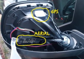
1) So as per paragraph 2/photograph 3 - this is not the only electrical block to disconnect before you take the 3 screws out that secure the mirror to the door.
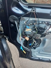
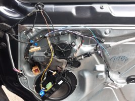
As I tried to extract the mirror from the door I found it was still attached to other electrical cables and had to reattach the wing mirror to investigate further!
(If you have wind deflectors then this may slightly impede the extraction/installation of the mirrors as well so you may have to re-fix the ends afterwards)
I wrongly assumed the other wires going through the door grommet were being fed back into the dash, these were in fact the 'Aerial' & 'GPS Aerial' which are attached to
the wing mirror.
Once the wing mirror and cable assemblies are fully extracted from the door you can then feed the aerial cables through the rotating aperture from the door side to the
mirror side intact.
The new wing mirror rotating aperture is slightly smaller than the originals but the cables will still go back through intact albeit I had to slightly curve the earthing clip
shown above.
2) As above the earthing point is not present in the new mirrors so I drilled out the earthing wire to accommodate the securing screw - anyone see any problem with this?
(Q1)
The mirrors were screwed back onto the door without further incident.
Page 5 which should be Page 3!



Page 5:
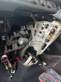
1) As per the above instructions I removed the end panels and used the ignition key to disarm the airbag on the passenger nearside (don't know if the latter is entirely
necessary!)
I removed the panel underneath the light switch and the matching panel on the left hand side I assume is the glove compartment which is secured by torx screws.
2) You can now access the torx screws locating the central curved trim below the gear lever and after removal it left me with the exposed areas as above. (Disconnect the cig
lighter)
3) The internals of the dash seem pretty exposed to install the new upgrade kit - is there anything else that needs to be removed to accommodate the new install? (Q2)
Page 3 & 4:

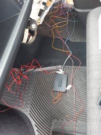
Page3 & 4:
1) I cannot locate the 'unused bracket' but I'm sure I'll be able to secure the module unit in there somewhere.
Has anyone else encountered this problem and do you have any pictures of where you secured it that didn't impede any moving parts or reinstallation of the trim
panels? (Q3)
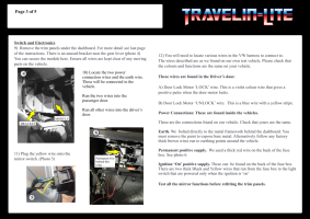
2) I found the description of where the wires go confusing and its just easier to lay them out as per the wiring diagram.

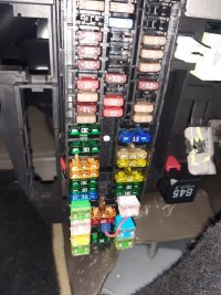


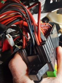
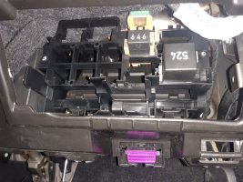
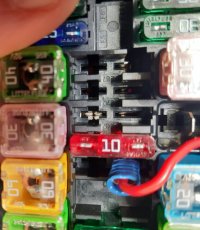
(The relays and fuses above reflect the location under my dashboard going from left to right)
3) Instructions - 'Permanent Positive Supply. We used a thick red wire on the back of the fuse box. See photo 6'
So photo 6 depicts a relay which looks like the relays on the R/H/S of the dash which I wouldn't describe it as the fuse box which I consider to be located in the centre
console!
So my next question would be can I take a feed from the relays on the R/H/S of the dash or would it be from 'a thick red wire on the back of the fuse box'? (Q4)
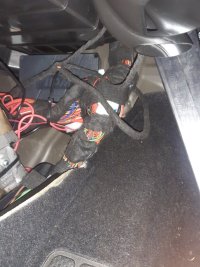
As you can see from the photos above there is already a modification for a dash cam and I'm sure there will be preferred positions for other modifications so if a feed is
taken from here then which 'thick red wire' would be the most suitable for this? (Q5)
4) Instructions - 'Ignition On Positive Supply'. Fuse Box, 2 thick Black and Yellow wires that run from the fuse box to the light switch - can't move for thick Black and Yellow
wires.
I cannot see any dual coloured black and yellow wires however there are obviously some big black wires there!
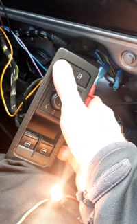
As per the photograph below, this is the connector for the light switch which has a yellow wire but I wouldn't consider it very thick!!
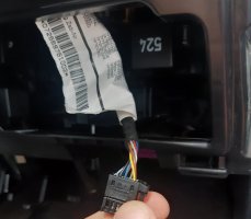
Can anyone give me a steer on this one? (Q6)
Last question for the time being reference the last 2 points and connecting the wires at the door ends - which is the best way to safely tap into the electrics (Q7) as
Travelite claim 'This is a complete kit and you wont need any other parts or accessories' ........... I think this is probably a bit misleading unless I'm supposed to wrap wires
around each other!
There are inline fuses so I'm assuming I could do something similar to the dashcam modification if there are any unused slots in the fuse box!
I haven't attacked the door ends yet but have seen some other threads on here and questions about the colour coding so I'll continue that later as I'm almost out of images
to attach anyway.
I obviously don't want to set my wiring loom alight so if someone can give me a few pointers or let me know what they did then I'll update this job from start to finish
PS my van is my primary mode of transport so the sooner I resolve this the sooner I can put it all back together as something like this shouldn't take more than a day to complete!
Stand fast - just found a thread from SAF1981 T6 Guru so I'll try and touch base with them first - Power folding wing mirrors from Travelinlite
T6 15-20 Electric Power Folding Mirrors (upgrade kit)
I consider myself pretty handy but the instructions provided are pretty poor in my opinion. PDF Viewer or see below
I've found a few threads already open on this subject and tried to troubleshoot this but to no avail so if permitted I'm going to start a new thread in the hope it solves my issues and maybe helps someone else out in a similar position!
So as per the instructions I'll take it from the top with questions in bold:
Page 1:

Page 1:
Got no problems with this as I've removed the door cards before and the information looks good.
Page 2:


Page 2:
1) So as per paragraph 2/photograph 3 - this is not the only electrical block to disconnect before you take the 3 screws out that secure the mirror to the door.
As I tried to extract the mirror from the door I found it was still attached to other electrical cables and had to reattach the wing mirror to investigate further!
(If you have wind deflectors then this may slightly impede the extraction/installation of the mirrors as well so you may have to re-fix the ends afterwards)
I wrongly assumed the other wires going through the door grommet were being fed back into the dash, these were in fact the 'Aerial' & 'GPS Aerial' which are attached to
the wing mirror.
Once the wing mirror and cable assemblies are fully extracted from the door you can then feed the aerial cables through the rotating aperture from the door side to the
mirror side intact.
The new wing mirror rotating aperture is slightly smaller than the originals but the cables will still go back through intact albeit I had to slightly curve the earthing clip
shown above.
2) As above the earthing point is not present in the new mirrors so I drilled out the earthing wire to accommodate the securing screw - anyone see any problem with this?
(Q1)
The mirrors were screwed back onto the door without further incident.
Page 5 which should be Page 3!


Page 5:
1) As per the above instructions I removed the end panels and used the ignition key to disarm the airbag on the passenger nearside (don't know if the latter is entirely
necessary!)
I removed the panel underneath the light switch and the matching panel on the left hand side I assume is the glove compartment which is secured by torx screws.
2) You can now access the torx screws locating the central curved trim below the gear lever and after removal it left me with the exposed areas as above. (Disconnect the cig
lighter)
3) The internals of the dash seem pretty exposed to install the new upgrade kit - is there anything else that needs to be removed to accommodate the new install? (Q2)
Page 3 & 4:


Page3 & 4:
1) I cannot locate the 'unused bracket' but I'm sure I'll be able to secure the module unit in there somewhere.
Has anyone else encountered this problem and do you have any pictures of where you secured it that didn't impede any moving parts or reinstallation of the trim
panels? (Q3)
2) I found the description of where the wires go confusing and its just easier to lay them out as per the wiring diagram.


(The relays and fuses above reflect the location under my dashboard going from left to right)
3) Instructions - 'Permanent Positive Supply. We used a thick red wire on the back of the fuse box. See photo 6'
So photo 6 depicts a relay which looks like the relays on the R/H/S of the dash which I wouldn't describe it as the fuse box which I consider to be located in the centre
console!
So my next question would be can I take a feed from the relays on the R/H/S of the dash or would it be from 'a thick red wire on the back of the fuse box'? (Q4)
As you can see from the photos above there is already a modification for a dash cam and I'm sure there will be preferred positions for other modifications so if a feed is
taken from here then which 'thick red wire' would be the most suitable for this? (Q5)
4) Instructions - 'Ignition On Positive Supply'. Fuse Box, 2 thick Black and Yellow wires that run from the fuse box to the light switch - can't move for thick Black and Yellow
wires.
I cannot see any dual coloured black and yellow wires however there are obviously some big black wires there!
As per the photograph below, this is the connector for the light switch which has a yellow wire but I wouldn't consider it very thick!!

Can anyone give me a steer on this one? (Q6)
Last question for the time being reference the last 2 points and connecting the wires at the door ends - which is the best way to safely tap into the electrics (Q7) as
Travelite claim 'This is a complete kit and you wont need any other parts or accessories' ........... I think this is probably a bit misleading unless I'm supposed to wrap wires
around each other!
There are inline fuses so I'm assuming I could do something similar to the dashcam modification if there are any unused slots in the fuse box!
I haven't attacked the door ends yet but have seen some other threads on here and questions about the colour coding so I'll continue that later as I'm almost out of images
to attach anyway.
I obviously don't want to set my wiring loom alight so if someone can give me a few pointers or let me know what they did then I'll update this job from start to finish
PS my van is my primary mode of transport so the sooner I resolve this the sooner I can put it all back together as something like this shouldn't take more than a day to complete!
Stand fast - just found a thread from SAF1981 T6 Guru so I'll try and touch base with them first - Power folding wing mirrors from Travelinlite
Last edited:


