How to disable split charge ?

Floor Fit

Member
T6 Pro
Hi can any one help , im just finishing installing a CBE 210cp control system in my van which has A factory leisure battery and regen ...... so i need to disable the split charge side of the CBE kit and the instructions are rubbish, the only reference to it says "to remove the batteries from parallel remove the R37 resister " which is fine but is that all that is needed ?? any one installed one ?? Cheers
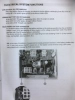
cbe 210.JPG
 
Why do you need to disable it, if you are not using the B2B function would you just not have anything connected to the output ?

Looking at that diagram there should be a resistor located on the PCB beside the 12 pin connector this will need to be cut, i would assume if you read the markings on the circuit board the resistor will be labeled R37, once you are confident you have the correct component you can snip the metal leg/s either side of the body of the resistor to separate it from the PCB and as per the instructions this should disable the desired function but remember unless you are very good at soldering its a one way ticket

If you are not sure post some pics of the circuit board and a close up of the area beside the 12 pin connector
 
Thanks Pauly - i need to keep the b1 and b2 connected for other functions to work , and i'm positive of the location of the resister can easily de-solder it and remove it. I was hoping someone else may had already done one :whistle::whistle:, once installed it will be tricky to test if its disabled until the van goes into regen . CBE tech help is only based in Italy so my question gets lost in translation.
 
It was all good , i kept the ignition feed and de-soldered the split charge resistor . The instructions supplied were pants . Its a fab bit of kit but TBH i only wanted it due to the funky display / control panel ;)

That’s good to hear. I’m looking at an all in one control system myself now.
If the CBE had the ability to control the heater then I guess that would be all bases covered!

Shame the Cali system + sensors couldn’t be used.
 
That’s good to hear. I’m looking at an all in one control system myself now.
If the CBE had the ability to control the heater then I guess that would be all bases covered!

Shame the Cali system + sensors couldn’t be used.
Not sure which heater you have, but the Erber do an app connect now so possible route ?
 
Dont snip the resistor out completely, or remove it by desoldering, just snip one end, whichever end is most accessible. Try to do it halfway along the silver wire. Lift the resistor slightly, and slide a bit of sleeving over it. Then if ever you need to revert to standard you just remove the sleeving, bend the resistor back into place and solder the one leg you snipped. Its astonishingly poor that they dont provide a header link for this, punters shouldnt have to modify circuit boards.
Cheers
Phil
 
Back
Top