CAN bus or Lin Bus

Thanks. From previous posts I was under the impression that these items are not on the LIN bus?

This is something I could look in to as well. locking the van remotely would be a big plus.

Where is the best place to tap into the Lin bus that will carry these messages?

This will probably be phase 2 as I have orders the parts for the can bus now.
 
When the vehicle is sleeping you wont have any CAN communication - thats how the whole thing gets into a low power state. There will be certain events that will prompt the vehicle to wake up, eg when you unlock one of the doors. Generally, the vehicle only wakes up for a very short time while it works out if this is a real wakeup or just spurious noise. Once you get a confirmed wakeup, the CAN will start running, ready for you to use it.
You do need to be careful with which CAN data is used. It's generally a good idea to avoid using gateway CAN messages as these may only be valid in certain ignition states (eg engine running). There will always be another CAN message which contains the data direct from the source module. The other thing to be wary of, is the values sent immediately after wakeup. You often get default values being sent until a module has worked out what the real value should be. Similarly the last data sent before going into sleep should be the right value, but this is not a given. I've worked on systems where the data is only valid under certain conditions.
I would avoid trying to get data from LIN if at all possible. It's a master-slave system so you will only get data if the master requests it. There may also be multiple LIN buses in the vehicle (because it's only used for localised communications) so you would need to tap into the correct one to get anything useful. Any useful data should also be present on CAN anyway.
One last point - it's generally not a good idea to be sending CAN messages while the vehicle is in sleep. This can cause all sorts of strange effects as the vehicle modules try to work out what's going on. Some modules will wake up and log all sorts of errors because they aren't seeing messages that they think should be being sent. It's also likely to cause havoc with battery drain.
 
Ok. So let’s separate the use cases of detecting what is going on in the van and actuating something, such as central locking.
  • For detection, listening the CAN is the way to go as discussed earlier
  • For actuating, I would go with GPIO pins and operate the actual switches, possibly through some buffer transistors or relays depending on the circuit
It is true probably both CAN and LIN can be used for actuations as well but information available for the actual messaging is much less known than the decoding schemes are. In addition, waking the buses up needs to be handled somehow.

So, I think going down the bus route wrt actuations will include quite a bit of investigative work, such as listening buses while playing with the keyfob and trying to later emulate that with ESP32. And taking good care nothing silly happens - eg a simple bug could lead to doors being opened up automatically in the middle of the night. Or not open anymore in hazard situations. Certainly an interesting project as well but a different ballgame compared to the original question!
 
Last edited:
Thanks. From previous posts I was under the impression that these items are not on the LIN bus?

This is something I could look in to as well. locking the van remotely would be a big plus.

Where is the best place to tap into the Lin bus that will carry these messages?

This will probably be phase 2 as I have orders the parts for the can bus now.
17pin bcm!
There are multi-steering buttons on the same contact (except ADAPTIVE CRUISE)
 
I know for sure that it is not very difficult to pretend to be a Lin Master and interrogate a subordinate module. (I'll do it with a smart battery terminal very soon)
 
It is quite easy to track the closing command in the LIN (read the tire when you pick up your car), but lifting the windows can also be tracked (holding the closing button leads to lifting all the windows)
 
If you use the LIN, you will have access to the control of the central lock and power windows.

Are you sure about central locking? I really don't want to downplay what you're saying, rather just add to my understanding.

I'm looking at T6 locking wire diagrams and there's no LIN here to be seen. Just one of the diagrams below but they all look the same. The lock units communicate with BCM directly through door contact switch wire, lock signal wire and central lock motor drive network. The motor drive network is shared among all doors. So, getting central locking through LIN (or CAN for that matter) would have to persuade BCM to actuate the lock motor network.

Now, LIN is a master-slave topology network where BCM in this case is no doubt the king of the hill. This basically means there's no way to command BCM to do anything by tapping on the bus as all messaging is initiated by the BCM. As far as I understand it is of course possible to emulate LIN messages sent by the BCM (fake master) but as the lock actuators are not controlled by slave nodes of the LIN network I don't really see how that could do anything with the locks.


1704535806998.png
 
Are you sure about central locking? I really don't want to downplay what you're saying, rather just add to my understanding.

I'm looking at T6 locking wire diagrams and there's no LIN here to be seen. Just one of the diagrams below but they all look the same. The lock units communicate with BCM directly through door contact switch wire, lock signal wire and central lock motor drive network. The motor drive network is shared among all doors. So, getting central locking through LIN (or CAN for that matter) would have to persuade BCM to actuate the lock motor network.

Now, LIN is a master-slave topology network where BCM in this case is no doubt the king of the hill. This basically means there's no way to command BCM to do anything by tapping on the bus as all messaging is initiated by the BCM. As far as I understand it is of course possible to emulate LIN messages sent by the BCM (fake master) but as the lock actuators are not controlled by slave nodes of the LIN network I don't really see how that could do anything with the locks.


View attachment 224514

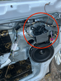
IMG_0709.jpeg
 

J386 and J387, although called door control modules, are integrated with the window motors. These lumps at the front part of the doors:

1704554971094.png

The central lock units are separate and located at rear part of door - they operate the locks (duh) and the pin that comes up through the door cards.

So yeah, door control modules are in the LIN but only deal with the windows and folding mirrors.
 
Last edited:
Back
Top