You are using an out of date browser. It may not display this or other websites correctly.
You should upgrade or use an alternative browser.
You should upgrade or use an alternative browser.
Wiring connections for Ring RSCDC30 charger
- Thread starter superchargedpolo
- Start date
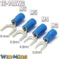
You want a straight pin terminal connector; something like these:-
http://m.ebay.co.uk/itm/Insulated-S...3D191961168060&_trksid=p2056116.c100408.m2460
http://m.ebay.co.uk/itm/Insulated-S...3D191961168060&_trksid=p2056116.c100408.m2460
@superchargedpolo looks like you stuck that last one up as I was typing. They are the same as what I have on the stranded cable that goes into the consumer unit in my van. They are certainly what Travelvolts uses as he gave me a few.
@superchargedpolo looks like you stuck that last one up as I was typing. They are the same as what I have on the stranded cable that goes into the consumer unit in my van. They are certainly what Travelvolts uses as he gave me a few.


The crimp connection to cable is another point of resistance.. And in this case an unecessary one..
Are home consumer units wired using crimps nowadays, or straight into these screw down blocks? As that's 240/3phase, and higher amps, and this is a mere 12volts system, all be it 30amps odd..
Over to the Sparks....
Are home consumer units wired using crimps nowadays, or straight into these screw down blocks? As that's 240/3phase, and higher amps, and this is a mere 12volts system, all be it 30amps odd..
Over to the Sparks....
Google bootlace ferrules as per the pic above, similar connector but the cable goes inside the point of entry rather than the crimp extending out from the end of the cable, these do require a unique crimper though but for the size of cables you are looking at not overly expensive
Last edited:
Perhaps the difference is that 240v systems use solid core cable? I dunno not a sparky.The crimp connection to cable is another point of resistance.. And in this case an unecessary one..
Are home consumer units wired using crimps nowadays, or straight into these screw down blocks? As that's 240/3phase, and higher amps, and this is a mere 12volts system, all be it 30amps odd..
Over to the Sparks....
That's exactly what I was trying to refer to, cool to know the name of them.Google bootlace ferrules as per the pic above, similar connector but the cable goes inside the point of entry rather than the crimp extending out from the end of the cable, these do require a unique crimped though but for the size of cables you are looking at not overly expensive


Boot lace ferrule. That's what I was after, ta.
The reason for the multi strand cable in automotive use is to stop fatigue through vibration, and easier conformability and reliability. As well as threading of multi cable looms in the manufacturing stage..Perhaps the difference is that 240v systems use solid core cable? I dunno not a sparky.
Ferrules are normally used on stranded cables in control panels and connectors that are taken in and out for testing and commissioning to reduce the risk of splaying and shorts etc.
On a large 6mm cable in this situation I normally just tin(solder) the ends.
On a large 6mm cable in this situation I normally just tin(solder) the ends.
Ferrules are normally used on stranded cables in control panels and connectors that are taken in and out for testing and commissioning to reduce the risk of splaying and shorts etc.
On a large 6mm cable in this situation I normally just tin(solder) the ends.
Likewise and my RSCDC30 is working well including with a 100W Solar panel attached.
I disagree with the solder option as it does not allow the conductors to conform to the shape of the terminal and presents a limited surface which in extreme cases can be a point of high resistance. The ferules are the best option.
Pat Connolly
New Member
What size cable from the charger to the batteries would this unit need?
cheers
cheers
6 mm in and out.
Similar threads
- Replies
- 18
- Views
- 1K
- Replies
- 11
- Views
- 1K
- Replies
- 64
- Views
- 3K
- Replies
- 12
- Views
- 1K
- Replies
- 3
- Views
- 525


