VSR to Ctek DC-DC

Frazman

Caledonian Camper Conversion
Hi all,

I see this topic has been approached a couple of times, but I’m looking for some specific guidance to enable me to replace my existing VSR with a CTEK 250SE.

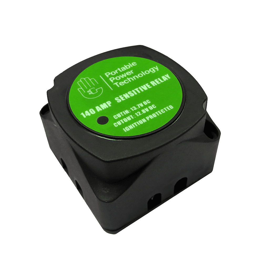
So, I’m aware I need to create a ignition feed and run it to my new charger. The existing VSR says it’s ‘ignition protected’, whatever that means?

The VSR has 2 x positive feeds running to it, which I understand will go straight onto the relevant terminals of the ctek. Sorted.

The VSR also has a thin black negative wire incorporated into the negative feed cable from the leisure battery, which should become redundant and unused when I wire up the ctek as it’s too thin to be used as a ground for the ctek.

Regarding the earth wire for the ctek - the instructions advise this be a 4mm cable. Am I best routing this direct to my chassis earth or to the negative terminal of the leisure battery? If this makes any difference?

I’ve added some pics below of my existing setup put in by a professional converter. As you can see, space is tight and I’m having to work upside down with my head inside the cupboard!

any help or advice would be much appreciated.

78E17B31-5AE1-4DA1-B59C-7D556D544602.jpeg

7FB379DD-35D5-40B0-944D-FE0362DFB6AB.jpeg

E5973A72-9251-4B2C-9667-037BB2CB5537.jpeg
 
Last edited:
the two fat cables are the main battery POS feeds.

it looks like the STARTER "sense feed?" is doubled up with a second cable? - not sure where that is going?.

the small thin black is just a 0v NEG that is needed for the VSR to work.


1622902616463.png


...


so for the CTEK,

just connect both battery ring terminals to the D250.

give the D250 a 4mm 0v NEG from either a body/chassis ground or the leisure battery 0v NEG

The battery select cable will need setting - depending on your battery type. ( 0v NEG for AGM battery type)

The RED smart alternator will need ang +12v POS IGN pick up for smart alternator setting.

1622902887852.png


.


.


more info here:


.
 
**************************************************
Dellmassive`s -- "how I Done It" -- Thread
**************************************************
Kit List And Stuff -- How I Done It & What I Use --
**************************************************
VIP Membership | VW T6 Forum - The Dedicated VW Transporter T6 Forum
************************************************
For Sale - Summer-weekend-t6f Limited Edition External Stickers
For Sale - T6F Flags
**************************************************
 
Many thanks @Dellmassive.
I have no idea where the second live cable goes to/from, will try and narrow it down today. cheers for sharing the info, loads of useful guidance in there.
 
Last question, I’ve been digging through your guide and can’t find any mention of cable size for the ignition feed.
I take it some 2mm cable, the same as the short section already attached to the ctek will do?
 
yes that will do it . .

1.5/2.0/2.5mm2(sq) will do it.

its just a input signal so wont draw a large current.

some info here:


.


come join the VIP club for more:


+++


+++
 
have a look at this example: (2.0mm / 25A /10M)

make sure its fused at source, say at 5A(keep it low).


1622979295316.png
 
Many thanks @Dellmassive.
Managed to work out what the extra positive wire was from the Sargent EC155 manual; It contains brown and green wires, showing on the instructions as ‘vehicle battery’ and is fused separately at 20A....Seeing as it was doubled up on the VSR with the vehicle battery feed, I assume this is for providing a charge when on EHU.
Could this cause any issues with the Ctek? I’ll be testing it tomorrow so fingers crossed all works ok!
 
Last edited:
not sure without testing.

EHU - Sargent has a very basic 12v power supply that can help charge the leisure battery when engine off and on EHU.

if its also connected to the starter battery . . . it may trigger the Auto VSR feature on the CtEK. - i suppose same as the VSR setup?

it will all depend on the voltages of the starter battery, the leisure battery and the EC155 charger voltage as to which way any current will flow. ( Highest voltage source will flow current to lowest voltage source)

dont know is the honest answer. ( i havent got a EC155 to test )

keep us posted . . .

and post some pics
 
Not really, none of the how to videos feature a consumer unit. But thanks anyway!

I’ve wired up the CTEK like for like to the VSR’s configuration and all seems to be working well (so far!) lights all ok etc.

The wiring to and from the consumer unit is mind boggling. The double live on the same terminal actually comes direct from the EHU and also from the consumer unit. I wouldn’t have thought it was possible to put 230V through this way, but if the VSR coped before I see no reason why it should cause any mains charging issues. Hopefully.... I’ve emailed Caledonian for clarification but won’t hold my breath at getting a reply!
 
5074D8FA-40F8-40B5-B68D-E769C725569A.jpeg
1 - positive cable from Ctek to consumer containing brown and green wires marked ‘vehicle battery’ on Sargent wiring diagram

2 - positive cable from EHU point to Ctek.

775C33A8-6672-4034-9A96-A3246646C57F.png
 
Apologies if I've got the wrong end of the stick totally, but..........the CTEK should only link the two batteries, with possibly a solar input. I'm not sure why you want to link the EHU to the CTEK? I presume by EHU, you mean mains charger from the EHU? EHU/mains charger should go to the leisure battery directly surely? The CTEK has an upper voltage limit (23V from memory) for solar, so I'm assuming running a mains charger could fry it.

Where's the positive in from the starter battery on there (cable 2?)

From elsewhere: "............a regulated mains power supply (can be used) to feed into the solar input for the CTEK when on mains hookup (max voltage 23v). They'd fitted a relay to switch the input between solar (when not on hookup) and the PSU when hookup was connected."

The only reason to do this would be to trickle charge the starter/vehicle battery once the leisure battery was charged. With no solar, you wouldn't need the relay mentioned, the mains charger input would go direct to the solar input on the CTEK (I'm presuming that's cable 1 on your pic?).

What power source is lighting the orange lights on your photo - just the van ignition?

Assuming you have an AGM battery, you should also have the thin black 'battery select' wire coming from the CTEK to earth. Where is your leisure battery (I presume just below and that's the silver battery securing strap in your upper pic?). There's obviously the temp sensor to fit to it too.
 
Last edited:
This is exactly my concern. However, I’m only replicating the wiring which was on the VSR to the Ctek.
Surely transferring the wire which comes direct from the hookup and putting it straight onto the leisure battery would fry that too?? I.e 230V put onto a 12V battery?

Temp sensor still to be attached, along with battery placed in. Picture isn’t complete set up - Space is extremely limited, I’ve spent the past two days upside down and resting on my head tinkering with this thing!
 
I’ve checked the combined voltage on the terminals. With the Sargent EHU charger turned on there is 12.5v going in and 13.5v DC volts coming out to the leisure battery. Also checked the AC Volta which gives 26.4 in and 28.8 out, respectively.
 
As above, the CTEK should sit between the starter battery and the leisure battery, so should (in your case) only have:
positive connection to starter battery +ve
positive out to +ve on leisure battery
negative out to earth on chassis
thin red wire to ignition switched +ve
temp sensor attached to leisure battery.

Any charging from mains hook up must involve a separate battery charger such as a CTEK MX10. EDIT - Sounds like the Sargent has a built in charger? If it has to go to the CTEK, I'd put it on the solar input, but would want to know details of the charge.

There's loads of info in Delmassive's blog links above.
Once the charger is connected to the leisure battery, all of the consumer stuff/circuitry should be 'downstream' of the leisure battery - so a +ve cable out from leisure battery to consumer unit/fuse box/bus bar whatever and -ves to earth. There should be nothing else going into your CTEK, unless you add a solar panel. If you have a solar panel now, it will be connected to a solar controller and then to your leisure battery. Ideally you would lose the solar controller and go straight to the CTEK (though if it works now, leave it connected to the leisure battery as it is - I'm having problems with my CTEK charging via solar)
 
Last edited:
I’m afraid this is now way beyond my abilities now. Having disconnected both inputs and turned on the charger, (Ctek now only earthed and output to leisure battery connected) there is an output charge of 13.v.... which makes it more confusing.


checks with the multimeter at various points didn’t show any dangerous/excessive voltages though so I will leave it as it is but remove the fuse for the mains charger. Think I’ll get a professional to look over it.
 
It shouldn't be too difficult - I think you've overthunk it....

Let's rewind a little. What vehicle is this in? A Bluemotion, start/stop T6? If not, why are you replacing the VSR with the CTEK?

If it is a vehicle with smart alternator, watch the video I linked (you can start at 4:25, as you have the cables in the correct place already).
Ignore all the EHU/mains charger/consumer unit stuff. You are just connecting the starter battery, to the CTEK, and the CTEK to the leisure battery.

Find the +ve from the starter battery (cable 1?) - connect to +ve in on CTEK.
Disconnect the other input (cable 2) from the CTEK and leave it for now. Once on hook up, check the output V and A on it and then think about connecting to the solar input on the CTEK
Check you have +ve output from CTEK to leisure battery (fused) and -ve connection to leisure battery -ve and chassis earth.
You have the switched ignition cable connected (red) - is that to the correct position? Watch the video from 6 min 17secs.
 
Last edited:
the Vehicle is a T6 with Euro 6 engine. I understand the installation of the Ctek is simple, and shouldn’t cause any issues BUT the complexity of the wiring to and from the consumer unit and how it is mostly concealed due to being taped up, and stuck in the depths of the wheel arch hasn’t made things easy!

I’m very appreciative of all the help given but I've spent long enough on it trying to get its orated for this weekend, will get an auto electricIan or a local converter to cast an eye over it at some point.
 
Back
Top