How to fit a DC-DC / battery-to-battery charger kit

I've bought a cheap "Relay 100" to dismantle, to see how easy it is to convert to a plug
afro.gif

 
I've bought a cheap "Relay 100" to dismantle, to see how easy it is to convert to a plug
afro.gif
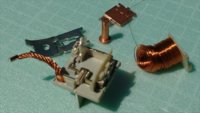
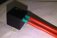
The relay arrived this morning, its the correct fit and as expected. The top pops off easily and all the tags are easily identifiable within the relay, so its a trivial task to either disconnect the coil and leave the mechanism in place, or remove the coil & armature to make a neater job. Inside the case, all the internal contacts have a large exposed metal surface, so soldering suitable cables should be straightforward.
Cheap, instant B2B plug for your Ctek or whatever, no mods to the van wiring and instant reversion to standard if needed
afro.gif

Cheers
Phil


relay100.jpg

plug100.jpg
 
Last edited by a moderator:
Took the advice and ordered a cheap (~2€) relay from China which has right connectors. Pleasant surprise was that contacts have quite large exposed metal area which willingly accepts soldering. Also the base was well heat resistant as the cables soldered were 6 mm2 (about AWG 9) thus needing proper heat up.

Having it now as a plug instead of two separate spade connectors also eliminates having energized open male connectors when disconnected (Ctek Smartpass 120).
Relay-plug_a.jpg
 
OK, we have taken this on board and can now supply the truly plug and play option for the variants using the single battery factory upgrade with relay 100. This also incorporates the ignition supply and a negative for those chargers that require it for battery type selection. Fully potted.

20181113_102130.jpg
 
I have fitted the plug and play kit from Travelvolts today on my Caravelle with factory leisure battery. It was fairly straightforward once I’d satisfied myself what to connect where. There were no specific instructions supplied but I worked it out easy enough using a multimeter.

I What I don’t understand is where the control wire is fed from. It is what switches the split charge relay on, but is it on full time when the ignition is on, or is it on just when the alternator is running?
Only when the engine is running.
 
I have fitted the plug and play kit from Travelvolts today on my Caravelle with factory leisure battery. It was fairly straightforward once I’d satisfied myself what to connect where. There were no specific instructions supplied but I worked it out easy enough using a multimeter.
Don't suppose you got any photos by any chance? I have a multimeter but no clue how to use it to identify what connects where.... I have the plug and play kit from Travelvolts too but although I received a PDF of instructions it isn't in enough detail for me.
 
Step 4, Remove factory split charge relay.
Remove the 2 screws holding the relay to the mounting plate and the 2 screws holding the mounting plate to the seat base.
View attachment 19093
Thanks for the guide, Loz. I made it as far as here but my setup looks nothing like this, I do not see the factory relay, although my Velle was deffo specced with factory leisure battery (I have the order details with all the options, came with the vehicle). Argh!

I have the factory starter battery and a factory leisure battery. Mine is a LWB with 204PS and is SE with tons of options incl comfort dash, electric & heated seats etc.

I have aftermarket towbar electrics (ECS 5F010 CAN Bus Trailer Module and an ECS 20 201 101A 12V 20/30A) under the passenger seat. I have an aftermarket inverter (Mercury Soft Start Modified Sine Wave 600W 12V) under the driver's seat, disabled for power saving. The inverter supplies two mains sockets in the rear, these also have two USB sockets each. There is an aftermarket switch on the dash which disables these extra USB sockets (not sure why it doesn't also disable the mains sockets).

I took a bunch of photos, can anyone help me identify what is going on and/or help me with my CTEK install?

20210403_155927.jpg
20210403_155942.jpg
20210403_160023.jpg
20210403_161958.jpg
20210403_162337.jpg
20210403_162357.jpg
20210403_162417.jpg
20210403_162437.jpg
20210403_162444.jpg
20210403_162614.jpg
20210403_162621.jpg20210403_162631.jpg20210403_162642.jpg
 
Thanks Loz! Are you able to help me understand how to adapt your guide to my setup? Whilst I am confident I could have followed your guide, much more knowledge than I possess would be required to be able to follow the instructions I received from travelvolts.
 
My instructions refer to the California split carge realy that is a larger 150A relay used when you have 2 leisure batteries, the connections are bolted on to the terminals and therefore easy to remove and connect to the dc-dc charger.
You have the single battery setup that uses the 100A relay, seen in your photo with 100 on the top. As the connections for this relay are made into the relay base it’s not so convenient to remove them. For this setup @travelvolts supplies a loom kit that simply plugs into the relay base in place of the relay.
 
Hello, I read this great instruction and bought this dc-dc charger:
"victron orion-tr smart 12/12-18a" and just realized that this unit does not have place for ignition conector from original vw vsr.
Does anybody know if I can connect just live wire from starter battery and from leasure battery on victron charger and will it work without ignition wire?
I have T5.1 2010. with factory installed aux battery?
Thanks in advance...
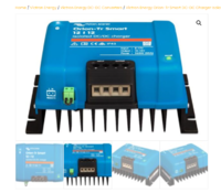


the IGN feed goes to the green block


1617817042345.png


example:


+++

hi ***.

heres mine (victron orion)

1x +ve main fused power from starter battery
1x +ve main fused power to leisure battery
2x -ve ground cables to chassis (due to orion being isolated)
bothe batterys also have there own -ve to ground


and 1x ignition feed to the Remote-H input from the SC fuse box.

you can use a fuse tap to pickup an ignition feed from any of the center line of fuses.

=

20191023_160050-jpg.53146

.


20191023_160106-jpg.53147


.


more details here > Dc-dc Charger (for Leisure Battery) -- How I Done It --


and fuse tap here > VIOFO 4PCS Circuit Fuse Tap ATO, Mini, Micro2, Mini Low: Amazon.co.uk: Electronics


upload_2020-1-20_20-25-10.png


Dellmassive`s -- "how I Done It" -- Thread
(MY18 T6 T32 204 DSG LWB)


+++
 
the IGN feed goes to the green block


View attachment 111722


example:


+++

hi ***.

heres mine (victron orion)

1x +ve main fused power from starter battery
1x +ve main fused power to leisure battery
2x -ve ground cables to chassis (due to orion being isolated)
bothe batterys also have there own -ve to ground


and 1x ignition feed to the Remote-H input from the SC fuse box.

you can use a fuse tap to pickup an ignition feed from any of the center line of fuses.

=

20191023_160050-jpg.53146

.


20191023_160106-jpg.53147


.


more details here > Dc-dc Charger (for Leisure Battery) -- How I Done It --


and fuse tap here > VIOFO 4PCS Circuit Fuse Tap ATO, Mini, Micro2, Mini Low: Amazon.co.uk: Electronics


upload_2020-1-20_20-25-10.png


Dellmassive`s -- "how I Done It" -- Thread
(MY18 T6 T32 204 DSG LWB)


+++
Thanks a lot mate..I read only step by step instruction without comments than realized that I bought 'wrong' charger..you saved my day...
 
Thanks a lot mate..I read only step by step instruction without comments than realized that I bought 'wrong' charger..you saved my day...
the Remote setting is configure via the APP . . .


more info over here:


.
 
the Remote setting is configure via the APP . . .


more info over here:


.
HI Dellmasive,
I do not understand :
' and 1x ignition feed to the Remote-H input from the SC fuse box '
Is the Remote-H terminal on charger? and where is SC fuse box ?
Sorry for my limited english understanding..
 
Back
Top