Adam_T6

Senior Member
T6 Pro
Hi,

I have started collecting parts to retrofit air con to my van. Has this been successfully completed by anyone? I see it is commonly done on T5s but only an aftermarket kit is fitted by Alpinair to the T6.

Does anyone know of any other parts required or have any wiring diagrams etc?


Thank you.
 
Last edited:
Thank you, I’ll update this as I go. Any info/help is appreciated.

Parts collected so far:
Condenser 7E0820411F
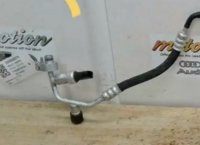
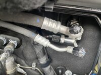
Air con pipes
Pump
3x pump bolts N91204501
Complete heater box with loom
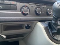
AC heater controls (no rear demister) 7E0907047T
Dash trim surround for controls 7E0857304D

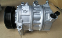
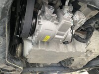
Compressor/pipework
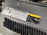
There are many variants of compressor, you need to find one to suit a single evaporator. Also from 09/2016 the refrigerant changed from R134a (13mm/16mm pipe fittings) to R1234YF (14mm/17mm pipe fittings). So it’s necessary to match the pump and pipe work.

Gas quantities (single evaporator)
R134a - 600g
R1234yf - 530g

Oil type/quantity
R134a - G 052 300
R1234yf - G 052 535

R134a
  • Denso compressor (part No. 7E0 820 803 Q) = 170±10 cm³
  • Sanden compressor (part No. 7E0 820 803 M) = 60 cm³
  • Denso compressor (part No. 5Q0 820 803 F) = 110±10 cm³
  • Denso compressor (part No. 7E0 820 803 N) = 170±10 cm³
  • Denso compressor (part No. 7E0 820 803 P/R) = 150±10 cm³
R1234yf
  • Denso compressor (part No. 7E0 816 803 D) = 250±10 cm³
  • Sanden compressor (part No. 7E0 816 803 B) = 60 cm³
  • Denso compressor (part No. 7E0 816 803 C) = 170±10 cm³
  • Denso compressor (part No. 5Q0 816 803) = 110±10 cm³
Wiring info

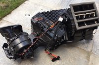
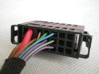
The connecter that the heater box loom (attached to the heater box) plugs in to on the van is not there. The part number for the plug is ‘6Q0972777’.

T17A (connector above heater box)

1 - Fan +12v (red/yellow) - from old fan switch (black/blue) T5F pin 1
2 - Fan earth - from old fan motor (brown)
3 - N/A
4 - N/A
5 - +12v Fuse 15 on holder C (red/grey)
6 - Ground (blue/red)
7 - AC compressor + (pin 1) (brown)
8 - Pressure sensor (pin 2) (brown/black)
9 - Residual heat relay (yellow/ green)
10 - N/A Heated seat (pink/ yellow)
11 - N/A Heated seat (orange/black)
12 - CAN+ (connect to radio twisted pair)
13 - CAN- (connect to radio twisted pair)
14 - N/A rear heated screen(green/brown)
15 - N/A coolant shut off valve
16 - Centre vent temp G191 (brown)
17 - Centre vent temp G191(brown) ground

3EB3B9B1-F7A4-4EBD-A52C-295FA343318F.jpeg

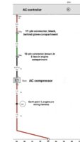
Compressor (N280):
6D62E33B-D821-40AD-85A0-99C7CDDC3132.jpeg
Connector part number - 1J0973702
Pin 1 - pin 16 of heater controller 20 pin black plug
Pin 2 - ground
5ABBDEC6-8F1C-4893-9DC4-65770F53CA92.jpeg


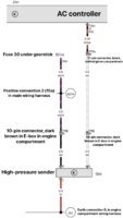
Pressure sensor (G65):
844FD74B-D7B2-48F9-8C36-5B654B5B3368.jpeg
Connector part number - 3D0973703
Pin 1 - ground
Pin 2 - pin 5 of heater controller 20 pin black plug
Pin 3 - SC30 in fuse box positive connection
CF5DC413-5E0D-4948-8B81-5F2B2BFF569A.jpeg

Connection locations
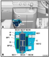
SC30
SC30.jpg
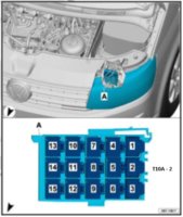
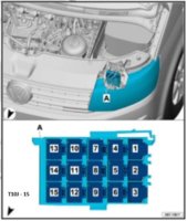
T10A
T10A.jpg
T10J
T10J.jpg
T17A
T17A.jpg
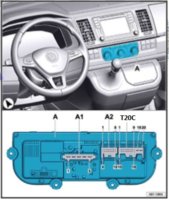
T20C
T20C.jpg

Drive belt to suit AC
03L903137AC

All seals, fixings & mounting brackets
5x Bolt N10414402
2x 8E0260759AD
2x 3D0260749C
2x 4E0260749B
1x 4E0260749A
1x N10347103
1x 4D0260749B
1x 8E0260749C
1x N01508210
1x 7E0820774A
1x 7E0820775
1x N90252104
1x 7E0820770
1x N10704501
1x 3W0971838
1x N90528204
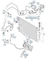
0EEEA68A-A592-48C9-89E0-67D5027D1283.jpeg
 
Last edited:
No heater valve (N422), heater valve relay (J541) or coolant pipework changes required, thanks to @Pauly for the confirmation.

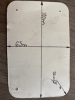
Template for bulkhead hole, measurements taken from AC model (old heater box in photo):
C8AD2B0F-2F5B-4C66-A994-A01969F98538.jpeg
3FE38457-04F8-4680-951F-5867394DD5E1.jpeg
61C8453F-1E5A-4C29-BF6B-DB5BC5DD539D.jpeg

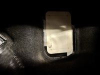
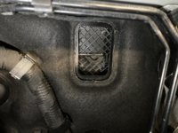
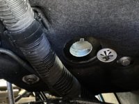
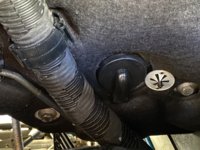
Evaporator drain (7H2820752) 32mm hole:
7BDD885D-DD27-4AE9-B5A4-116107FFC598.jpegDBE94A2F-8505-4A78-A713-8A76DDE010D5.jpeg

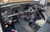
Heater box removed
D16971A0-5555-4182-A5EF-B34A8100E86F.jpeg

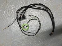
Wiring loom:
508379BF-710D-4A7E-892B-19FC5D9324C1.jpeg

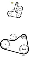
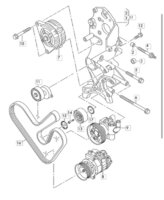
The auxiliary belt is obviously different, but it also takes another route with an additional idler (03L145276):

99C611BD-348B-4C1C-BDC1-EB6C8F8E9E1A.jpegDC8CD5CE-E150-4421-BD2C-107EE03D0B29.jpeg

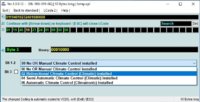
VCDS coding

Engine control module
Long coding
Byte 3
Select '02 Biderectional Climate Control (Climatic) installed'

VCDS.jpg
 
Last edited:
I sourced most of the parts second hand over a good few months where possible, otherwise I can imagine the parts cost would soon be £2/3000 from VW.
 
Hi @Adam_T6 Amazing job you’ve done there.
I’ve been trying to figure out a few things about my factory fitted air con and seeing as you’ve fitted one I wondered if you could help.

Does the flow of cool air from outside the van always pass through the evaporator even when the air con is switched of or is it somehow redirected?

I can’t understand why my cool Air blower smells when the air con is off but okay when on.

nick
 
Air will always flow through the evaporator. Switching the air con on can sometimes automatically change it to recirculated air, rather than outside air (the dash light will illuminate).

You can get air con ‘cleaners’ which is probably worth a try?
 
Nearly finished my aircon retro fit .
Could you please tell me how do i identify the Can H and Can L wiring to tap into at the rear of the stereo?
 
Nearly finished my aircon retro fit .
Could you please tell me how do i identify the Can H and Can L wiring to tap into at the rear of the stereo?
For AC control unit
CAN H - orange/green​
CAN L - orange/brown​
 
Back
Top