12.5v OEM Light. Supply Query!

Arrow

Senior Member
T6 Pro
So I've installed 6 X OEM T6 led lights. Have them all working on a Auto/on/off switch. In auto they are just as normal wired off the standard loom in parallel. In ON I've taken a feed from the spare cable under my passangers seat that goes to the main battery then feeds the lights.

My question... When the Vans running I'm getting 15v from the battery supply as you'd expect but will this damage or cause any issues with the 12.5v rated LEDs?

When the Vans not running it's around 12.7 so no issues there but I'm worried about switching them to the ON while running incase this causes damage.

The OEM supply is regulated and never moved beyond 12.5v so any info would be great before I damage 6 lights!

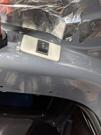
Looks the part in tailgate by the way. Really nice light output.

Thanks.

PXL_20210504_210031101.jpg
 
I've not metered it out yet . . . but i believe the rear lights are PWM controlled. (for the fade/dim)

which may be why you are seeing an RMS of 12.5v?

more info here:


***************************************************************************************
Factory Non-LED 3 wire setup:

(brown) - earth point left a-pilar
(brown/red) - connection 1 main harness (BCM switched neg 0v)
(red/black) - positive connection 1 main harness (BCM timed +12v) ( 7.5A fuse 24 holder C)
****************************************************************************************

Factory LED 2 wire setup:

(brown/red) - connection 1 main harness (BCM switched neg)
(red/black) - positive connection 1 main harness (BCM timed +12v)( 7.5A fuse 19 holder C)

****************************************************************************************


**************************************************
Dellmassive`s -- "how I Done It" -- Thread
**************************************************
Kit List And Stuff -- How I Done It & What I Use --
**************************************************
VIP Membership | VW T6 Forum - The Dedicated VW Transporter T6 Forum
************************************************
For Sale - Summer-weekend-t6f Limited Edition External Stickers
For Sale - T6F Flags
**************************************************
 
All my interior lights are run from my leisure battery which would be seeing 15v with the engine running and I have used the oem light with travelling lite bulbs in my rear hatch they have been working for 4 years with no issue
 
Yes they are BCM controlled when I put my switch to Auto, but when I switch them to constant on it bypasses the factory wiring as I've connected them directly to the main battery. This would be fine if the battery was at a constant 12.5 volts but when the Vans running I'm getting 15v. Just worried the increase in voltage will damage the LEDs. I'm trying to figure out how to keep a constant 12.5v supply (roughly)
 
you could try and use a Buck/Boost converter (voltage regulator) . . . on the leisure feed, to drop the 15v down to 12.5v. (2A/3A max per unit)

as seen over here: https://www.t6forum.com/threads/cab-ambient-mood-lighting-under-dash-how-i-done-it.16163/


1620365753184.png

1620365885798.png


About this item
  • 【High Precision】The buck converter consists of 36u thickened circuit boards, high-Q inductance with output LED indicator, and superior solid-state capacitors that can effectively filter out high frequency noise. Suitable for various electronic projects.
  • 【Input Voltage】DC 3V to 40V (input voltage must be 1.5V higher than the output voltage, no boost).
  • 【Output Voltage】DC 1.5V to 35V voltage is continuously adjustable, maximum output current is 3A.
  • 【Mini Size】45 * 23 * 14 mm (with potentiometer). 8pcs included.
  • 【Easy to DIY】Connect to power source, using a mini screwdriver to increase or decrease output voltage by adjusting the screw on the blue potentiometer and monitor voltage with multimeter to get the needed voltage, clockwise to increase voltage and counterclockwise to decrease voltage. (Factory default stays a high voltage, you need to contrarotate about 7-15 circles before the voltage starts ramping down, 1 circle means +/- 1V)


second option:

4 Pieces Adjustable LM2596S DC-DC Buck Converter Reduced Voltage Regulator Power Module 36V 24V 12V to 5V 2A Voltage Stabilizer with Digital Voltmeter Display

(2A/3A max per unit)


1620366000136.png

1620366094614.png
 
May be low value resistor in line with the 15v feed ?
You will need to measure the current drawn to work out what is needed, but it’s a cheap solution.

Pete
 
FWIW . .

15v accross the leisure battery would imply you are using a VSR or Split charge relay as part of your setup?

14.8v is the high setting from the alternator for the starter battery when its low or high demand electricals are switched on./

15.0v will be seen under regen braking.

maybe look at getting a DC-DC charger fitted, that will charge the battery better . ie AGM charge profile 13.6v etc.


more info here:


.


**************************************************
Dellmassive`s -- "how I Done It" -- Thread
**************************************************
Kit List And Stuff -- How I Done It & What I Use --
**************************************************
VIP Membership | VW T6 Forum - The Dedicated VW Transporter T6 Forum
************************************************
For Sale - Summer-weekend-t6f Limited Edition External Stickers
For Sale - T6F Flags
**************************************************
 
I think short term the buck converter is exactly what I need! Intention is to install a DC-DC charger once I've figured it all out.

I would have gone with a resistor had the voltage been stable to start with but it's 12.5 - 15v so need regulation.

15v was the max I seen it go while breaking yes, i don't have a split charger.

Think I know what needs doing!! :)
 
Voltage regulator installed. 11.14v seems to be the max it'll go with 14.7v on the input. Lights are still bright.

I might replace the little potentiometer with a dial one and mount it somewhere as it's got quite good dimming control. Doesn't heat up either which was a surprise.

Thanks for the advice.

16204988377886711425868398737607.jpg

16204988776485339295700308630629.jpg
 
sweet . . what Amps are the lights drawing? that PCB is good for 2-3A max.

if its not getting hot you may be under 1.5A?

nice meter BTW.
 
sweet . . what Amps are the lights drawing? that PCB is good for 2-3A max.

if its not getting hot you may be under 1.5A?

nice meter BTW.
Just measured and drawing about 1amp at 10.7v with the engine off.

The LEDs are around 4 watts each so not sure how it's drawing such a low current with 6 of them in parallel. Was expecting more like 2.5 amps.

I've had that meter for 11 years!
 
The LEDs are around 4 watts each so not sure how it's drawing such a low current with 6 of them in parallel. Was expecting more like 2.5 amps.
If the light fittings have maybe three LEDs and one current limiting resistor in series, the voltage across the resistor at 10.7V will be about half of what it would be at 12.5V. (as the LED's will have around 9V across them). Apply 12.5V and you may find the current doubles, and the power is indeed 4W.
 
If the light fittings have maybe three LEDs and one current limiting resistor in series, the voltage across the resistor at 10.7V will be about half of what it would be at 12.5V. (as the LED's will have around 9V across them). Apply 12.5V and you may find the current doubles, and the power is indeed 4W.
Yea that makes sense. Everything is all set up and tucked away out of site so testing isn't possible now. The lights are perfectly bright with the lower current so just going to leave it as is.

By the way, I used the little plastic cover on the top of the inner roof to install my switch which is a nice location to switch on/off with my big toe when in the bed!

Happy with the result. Thanks folks.
 

Attachments

  • PXL_20210504_210100500.jpg
    PXL_20210504_210100500.jpg
    65.6 KB · Views: 5
Back
Top